 Русский
 Français
 Chinese
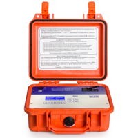
Comparison of new milliohmmeters produced by SKB EP
Measurement of active resistance of windings is an important step of maintenance and is mandatory for acceptance tests at manufacturers. Transformers, electric motors, electric magnets, etc. are subjected to vibration, overloads, temperature drops that with time lead to deterioration of contacts connections and require regular inspection by special instruments called milliohmmeters.
| MIKO-9 | MIKO-8M | MIKO-7M | |
 |
 |
 |
|
|
Scope of application |
|||
|
Windings of power transformers |
|
|
|
|
In-place checking of transformer OLTCs |
|
|
|
|
Windings of instrument current and voltage transformers |
at winding resistance of up to 30 kOhm |
at winding resistance of up to 10 kOhm |
at winding resistance of up to 2 kOhm |
|
Windings of electromagnets, electric motors and compensators |
|
|
|
|
High-frequecy filter windings |
|
|
|
|
Compensatory, current-limiting and other resistors of high-voltage circuit breakers |
|
|
|
|
Contacts and contact connections of power and signal circuits |
|
|
|
|
Cables |
|
|
|
|
Characteristics |
|||
|
Measuring range |
10 µOhm ÷ 30 kOhm |
10 µOhm ÷ 10 kOhm |
10 µOhm ÷ 2 kOhm |
|
Current rate range |
0.0005 ÷ 10A |
0.001 ÷ 10A |
0.01 ÷ 10A |
|
Insignificant error |
±0.1% |
±0.1% |
±0.1% |
| Best resolution |
0.1 µOhm |
0.1 µOhm |
0.1 µOhm |
Protection from:
|
|
|
|
| Non-volatile memory |
up to 1000 measurements |
up to 1000 measurements |
up to 200 measurements |
|
Display |
sensor, color, graphical TFT display (5") |
sensor, color, graphical TFT display (5") |
monochrome graphic display, 128х64 |
|
Instrument control |
directly and via computer using USB-cable or RS485-cable |
directly and via computer using USB-cable |
directly and via computer using USB-cable |
|
Type of data transmission channel |
USB, Bluetooth |
USB, Bluetooth |
USB, Bluetooth |
|
Power supply an in-built battery |
|
on request, modification MIKO-8MA |
on request, modification MIKO-7MA |
|
Power supply |
|
|
|
|
Case |
composite case |
composite case |
composite case |
|
Dimensions, mm. |
270х250х130 |
270х250х130 | 270х250х130 |
| Weight with battery, kg | 4.0 |
4.0 |
4.0 |
| Weight without battery, kg | - | 2.7 | 2.7 |
|
Functionality |
|||
|
Special-purpose modes for measuring different objects with account of their specific features |
10 objects |
10 objects |
5 objects |
| Automatic or manual setting of measuring current |
|
|
|
|
Special mode of measurements in the inductance-free circuits (three methods of measurements start-up) |
|
|
|
| Ability to connect to three phases of a transformer and to perform measurements at automatic switch-over |
|
|
|
|
There is also a mode for resistance measurement across two windings simultaneously |
|
|
|
|
Automatic accounting of load inductance. Instrument automatically defines moment of resistance establishment and stops measurement |
|
|
|
|
Automatic inductance category after measuring |
|
|
|
|
Specialized mode of electric resistance measuring of winding of power transformers with OLTC. Instrument may not be switched off when switching OLTC |
|
|
|
|
"Heat test" mode (coling test). The testing procedure follows the requirements set forth in Item 2 of GOST 3484.2-88 "Power Transformers. Heat Tests" |
|
|
|
|
Demagnetization mode of transformer’s magnetic circuit |
|
|
|
|
Automatic calculation of relative deviation of winding electric resistance of three phases from each other |
|
|
|
|
Automatic conversion of linear electrical resistance of windings connected in a delta or star circuit to the electrical resistance of the phase windings |
|
|
|
|
Automatic conversion of electrical resistance of windings, measured at current temperature to electric resistance at certified temperature |
taking into account winding material |
taking into account winding material |
|
|
Automatic calculation of the deviations measured and reduced to certified temperature of electrical resistance of windings with respect to certified resistance values |
|
|
|
|
Automatic calculation of winding temperature according to its measured and certified value of electrical resistance and certified temperature |
|
|
|
|
In-place checking and express diagnostics of OLTC condition at any weather conditions without removing the contactor tank cover |
|
|
|
|
Construction of assessment diagram of OLTC switching directly on the instrument |
|
|
|
|
Defining of OLTC fault nature: for instance, identifying of interruption of current-limiting resistors, poor selector contacts, etc. |
|
|
|
The instruments is under tests and pilot operation for being entered into the RF State Registrar of Measurement Instruments. Its production is scheduled for the third quarter of 2017. Orders are welcome.