Русский
 Français
 Chinese
Analysis of graphs generated by the PKV instruments
Question:
What can be the causes of the MKP-110 circuit breaker rebound and over travel?
Answer:
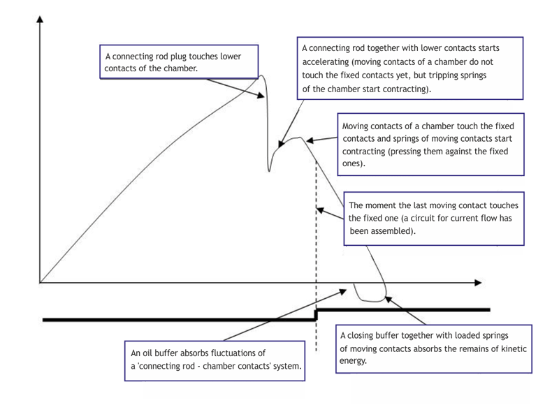
We will try to give our vision of the causes of the MKP-110 rebound and over travels on the example of the U-220 circuit breaker as principles of the U-.. and MKP-.. circuit breakers triggering/tripping are similar, but information available on the U-220 circuit breaker is more complete. The principle of the circuit breaker operation is shown in Fig. 1.
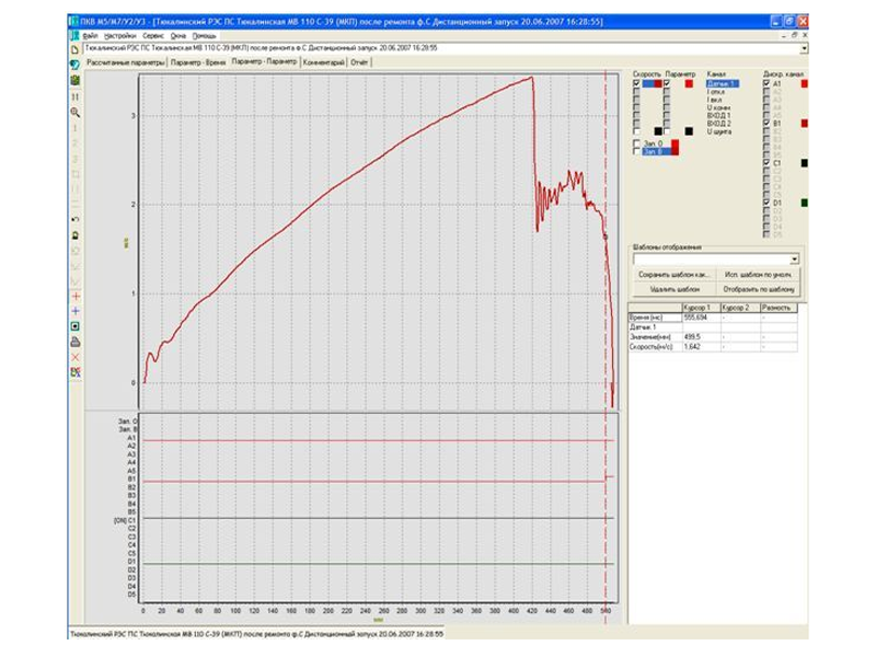
The circuit breaker is triggered following a command to the drive that starts moving a stem with a connecting rod upwards. After passing the section separating a connecting rod from a chamber, plugs of a connecting rod touch the lower contacts of a chamber. On the closing graph (Fig. 2) this is depicted as a sharp drop in the stem motion speed. Then a stem with a connecting rod pushes upwards the chamber plunger with bridges that connect fixed chamber contacts. After the bridge touches the fixed contacts the stem continues motion thus compressing the springs of bridges and pressing them against fixed contacts of the chamber. As the stem moves upwards, it rests against the spring-loaded closing buffer, whose full travel makes 20mm. During triggering a spring of the chamber disconnection is loaded.
Insofar as the moving parts have certain mass, then over travel of the rod and a related stem (i.e., the mobile parts by inertia travel over their equilibrium position) is considered to be a normal phenomenon. The problem is the magnitude of this overtravel.
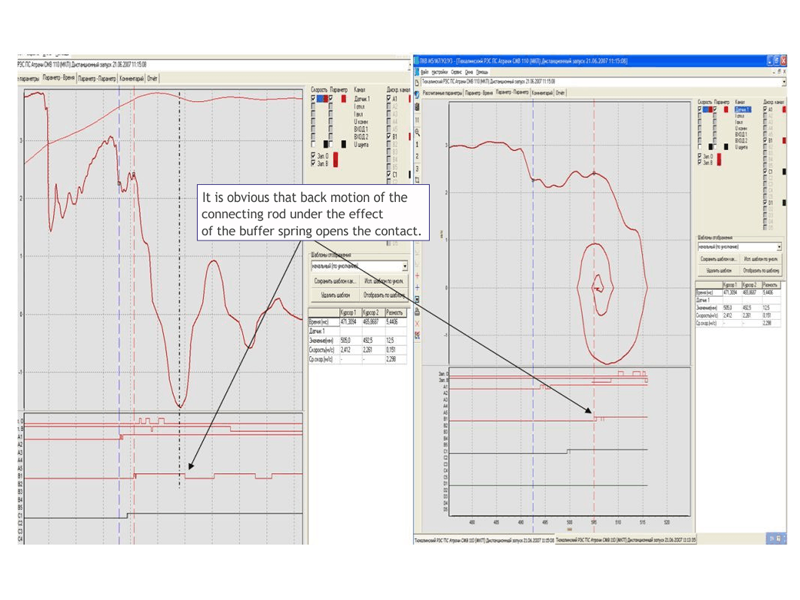
Under the impact of springs of a triggering buffer, springs of bridges and an opening spring of the chamber the connecting rod starts moving in the opposite direction thus reversing the circuit breaker stem. As the entire system has weight, then by inertia it can travel over its equilibrium position, forming a "rebound".

Question:
Travel in the U-110 circuit breaker contacts during tripping measured by lamps is different from that measured using the PKV instrument. Moreover, the travel in contacts measured by the instrument is almost half as low as that measured by lamps.
Answer:
The graph shows it as a short-term opening of the circuit breaker contacts somewhere in the middle of the travel. In our opinion, in this case we deal with loosened springs for the chamber contacts opening (or with extremely good opening springs of a drive). Upon tripping command the stem with a connecting rod due to tripping springs of a drive moves downwards faster than bridges of chamber that are activated by tripping spring of the chamber.
A connecting rod as if 'runs away' from bridges, and the circuit breaks in the point where the connecting rod plugs touch the lower contacts of the chamber rather than in the points of contacts opening by bridges. This situation is risky as initially the circuit is broken between the lower chamber contact and a connecting rod, rather than in the chamber, which can lead to unpredictable consequences.
Question:
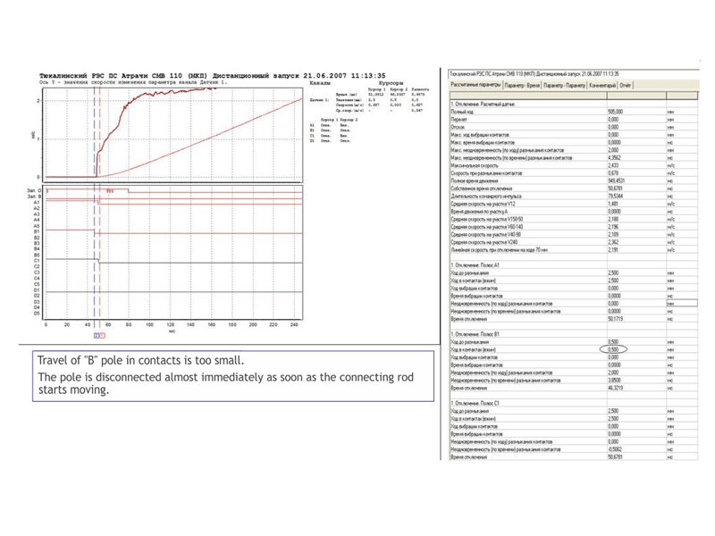
The travel in contacts is too small. The pole is disconnected almost immediately after the connecting rod starts moving.
Answer:
Springs of bridges are loose. Analysis of the circuit breaker triggering graph allows us to assume the following:
- Under the impact of closing springs of a drive the connecting rod touches lower chamber contacts and then moves the stem with installed bridges of fixed chamber contacts.
- At the moment the properly operating bridges touch the fixed chamber contacts, the stem with those bridges slows down, and the damaged bridge by inertia closes the corresponding contact of the chamber. Since a part of travel was passed by inertia, then according to displacement transducer, it closed the contact earlier than the subsequent closings took place during triggering (The first contact closing occurs at 504.5mm travel, subsequent ones - at 505.5mm).
- Then the closing buffer absorbs the kinetic energy of the connecting rod and a stem (with bridges), motion stops and the buffer spring pushes the connecting rod with bridges back.
- At the 505mm travel the stem moves the spring-loaded bridge and opens the contact.
- At the next move forward (by a drive) the bridge closes the contact at the 505.5mm travel again, and so on.
Thus, analysis of the 'B' phase closing and account of 'travel in contacts during opening' parameter (0.5mm for 'B' phase) allows us to assume that one of the springs of the chamber bridges is compressed or the point of this spring fixing to the stem is shifted downwards. For this reason the spring in closed status practically does not press the bridge against the fixed chamber contact.
Other versions of the fault:
- Chamber bridges are bent;
- A traverse plug was delocked;
- There were cases when the chamber after repair did not seat in place and the edge of its lower contact (a concave contact) was sat on the connecting rod plug. During operation the plug bent, sat in the chamber's center thus reducing the ingress.
Springs of bridges can loose due to destruction of a plastic cup isolating the spring from the contact casing. As a result, some current was flowing through it, heated it and 'released' it.
Another indicator of the lack of bridge pressing must be the pole resistance that to a great extent depends on the force of the contacting surfaces pressing against one another.
Question:
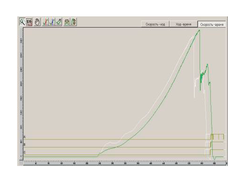
At the end of the closing process the speed graph is abrupt (U-220).
Answer:
Rapid break of the speed graph is due to peculiarities of its computation and graph construction. Unlike the speed graph, the travel graph is built so that under the lack of data (the stem did not move any more) the screen would show a continued line of the last travel value to the end of the screen.
Speed graph is built up based on the travel data array and if these data are not available (there is only a line of the screen), then it breaks. Therefore, this 'strange' speed graph is due to graph build up peculiarities rather than due to a circuit breaker. Thus, the graph break should be read as follows: the speed equals zero.
When the U-220 circuit breaker is triggered, a connecting rod usually travels over the final point and then goes back and seats on the latch. In your case the connecting rod smoothly came up to the final point, and the graph does not show the closing buffer operation. Probably the drive capacity is not sufficient for the circuit breaker triggering, or behavior of the air drive elements (due to low weight) differs from that of circuit breakers with the electromagnetic drive.
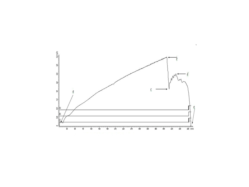
A diagram of triggering the properly operating circuit breaker with an electromagnetic drive is given in Fig. 1. After the connecting rod plugs touch the lower contacts of a chamber, the following stages proceed:
- A connecting rod continues motion, pushing moving contacts of a chamber.
- After the moving contacts touch fixed contacts, the traverse continues moving thus pressing the mobile contacts against fixed ones by springs.
- At the end of the motion a spring-oil closing buffer is actuated. The connecting rod passes its equilibrium position, and residual energy of motion is absorbed by this buffer. After that the connecting rod moves back and seats on a latch.
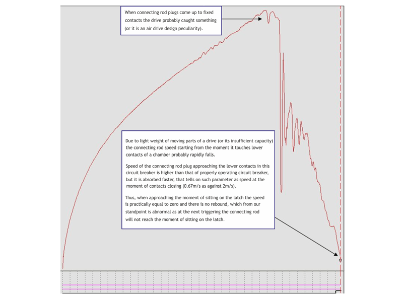
Pay attention to an idle tripping buffer (probably it has no oil). Under normal buffer operation the connecting rod travels over its final position when it moves forward (one over travel) and when it moves back (one rebound). Graphs of a reference and YOUR circuit breaker triggering are given in Figs. 2 and 3 (with appropriate comments).
Question:
How do 'wipes out/nippings' look like on the graphs recorded for the bulk-oil circuit breakers 35-220kV?
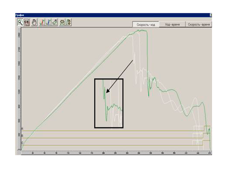
Answer:
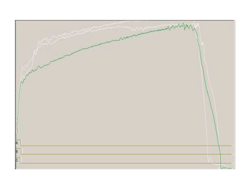
Speed vs travel graphs show 'wipes out' in phases and allow accurate detection of the defect location. Moreover, if in one case (Figs. 1&2) the availability of defect could be expected as the speed is lower than the rated one, then in another case (Fig. 3) all the time and speed characteristics corresponded to the reference data, i.e., following the standard measurements the circuit breaker was assumed to be properly operating.

Question:
How does clearance of mobile parts of a circuit breaker look like on the graph?
Answer:
Differences in the graphs of multiple measurements demonstrate the availability of this defect. All the time and speed characteristics at this defect correspond to reference data but clearances have already emerged that further may lead to the circuit breaker failure.