 Русский
 Français
 Chinese
The aspects that affect the quality of the high-voltage circuit breakers operation
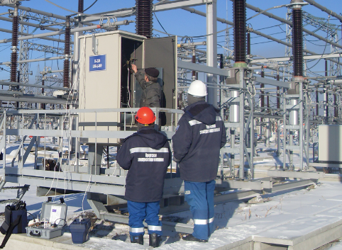
When there is a fault in the power line, the main task of the circuit breaker is to quickly and effectively solve this situation by disconnecting the circuit and isolating the fault from the power source. Quick opening reduces damage caused by high short-circuit currents that can damage equipment. Or, for example, in the modes of frequent reswitching of equipment at a substation due to seasonal changes in electricity consumption, reliable operation of circuit breakers is essential. This is why it is important to test circuit breakers to be completely sure that they function correctly.
Diagnostics of circuit breakers is carried out in accordance with the regulatory documentation. Depending on the types of circuit breakers (oil, air, SF6, vacuum), the set of measured characteristics to make a conclusion about the state of the circuit breaker may vary. In addition to measuring the formal parameters of HV circuit breakers, there is a number of tests that provide additional information about the state of the equipment. At the same time, this additional information can indicate incipient defects, when values of all the main parameters are within their ratings. One of the most common tests is to determine the speed and time characteristics of the main contacts, which directly shows the disconnection time. Consider a situation when a circuit breaker is taken out of service for testing, but it has not been used for a long time because it was in reserve. During the downtime, the switch components were not sufficiently lubricated, and the bearings may be corroded. These problems will slow down the first actuations. However, if at least one closing or opening operation is performed before testing begins, a self-cleaning is performed to remove traces of corrosion or stuck bearings, which will bring the breaker's response time to standard values. Therefore, when determining the actual time performance, this problem may not be present, and the service personnel will decide that this circuit breaker is in good condition and does not need further maintenance. But after some time, the fault will appear again, and this circuit breaker will not open quickly enough or will not open at all. Therefore, it is important to record the parameters of the first actuations, as this may detect incipient problems in the circuit breaker.
Measurement at the first actuation is part of an operational test, which provides a lot of useful information. Let's focus on three measured parameters: coil currents, control voltage, and contact response time. But, in addition, other parameters are also available – this is the response time of additional contacts, vibration, electric motor currents, travel and speed of contacts, etc.
Coil currents are measured, among other reasons, to detect any problems with lubrication inside the main bearings or in the latch. Analysis of coil currents can also show changes in resistance caused by short-circuited turns, burned coils, etc. The control voltage is measured during operation to indicate the status of the batteries. Before operation, the voltage of the station battery must be normal and controlled by chargers. However, the battery power consumption may be too high during operation. If this voltage drops below 10% of the rated voltage, it may be a sign of a battery failure. If the switch has three driving mechanisms, the winding currents and control voltages must be measured for each mechanism.
To perform competent diagnostics of high-voltage equipment, the personnel must have a clear understanding of the mechanisms and kinematics of the circuit breakers under study. Let's briefly consider the principle of operation on the example of an SF6 breaker.
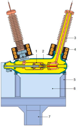
Fig. 1. Main elements of an SF6 circuit breaker:
1 Arc extinguish device; 2 Metal body; 3 Bushing; 4 Current transformer; 5 Load-bearing frame; 6 Control cabinet with drive; 7 Support;
Let's take a closer look at the arc extinguish device (1)
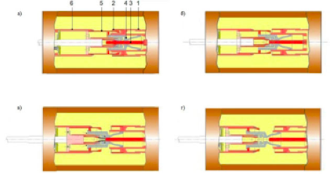
Fig. 2. Principle of opening
The components of the current circuit are the contact bracket (1), the base (6) and the movable contact cylinder (5). In the closed position (Fig. 2 a), the current passes through the main contact (2). In parallel, there is an arc extinguish contact (3). In the process of opening (Fig. 2 b), the main contact (2) opens, so that the current is supplied to the circuit passing through the still closed arc extinguish contact. When the arc extinguish contact (3) also opens (Fig. 2 b) during the subsequent execution of this switching operation, an arc occurs between its parts. Meanwhile, the contact cylinder (5) moves deeper into the base (6), compressing the arc extinguish gas contained there. The compressed gas rushes through the contact cylinder (5) in the direction opposite to the direction of movement of the movable contact parts, reaches the arc extinguish contact and quenches the electric arc.
When disconnecting a high short-circuit current, the SF6 gas contained in the area of the arc extinguish contact is strongly heated by an electric arc. This increases the pressure in the contact cylinder. In this case, the pressure increases to the level required for arc extinguishing without consuming power from the drive. During the further disconnection process (Fig. 2 d), the fixed part of the arc extinguish contact comes out of the nozzle (4). In this case, the gas rushes from the contact cylinder to the nozzle and quenches the electric arc.
Simultaneous measurement of time characteristics within a single phase is important when several contacts are connected in series. This circuit breaker works as a voltage divider, and if the time difference between the contacts is significant, then one of the contacts may have overvoltage. The tolerance for simultaneous opening of contacts for most types of switches does not exceed 2 ms.
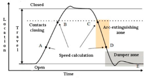
Fig. 3. Travel chart
A high-voltage circuit breaker is designed specifically for breaking the circuit at a certain short-circuit current, which requires actuation at a given speed to create the necessary cooling flow of SF6 gas (air or oil, depending on the type of circuit breaker). If the flow cools the electric arc well enough, the current is interrupted at the next zero transient. It is important to interrupt the current so that the arc does not light up again before the contact enters the so-called damper zone (Fig. 3, section DE of the curve). The speed is calculated by two points on the contact travel curve. The upper point is set by the distance (a measure of length, degrees, or percentage of travel) from: a) the position when the circuit breaker is on; b) the point where the contact closes or opens. The lower point is defined based on the upper point. This can be either the distance below the upper point, or the time to reach the upper point. The contact transit time between these two points is within 10 ... 20 ms, which corresponds to 1-2 zero transients. The distance at which the electric arc should be extinguished is usually called the arc-extinguishing zone (Fig. 3, section CD of the curve). Damping is a very important parameter for the mechanisms used to close/open circuit breakers. If the damping device does not function properly, mechanical deformations occur, which can shorten the service life of the circuit breaker and lead to serious damage. Damping in a breaking operation is usually measured by speed, but it is also possible to measure the contact transit time between two points located above the line that corresponds to the open position.
Existing diagnostics tools for high-voltage circuit breakers can record all the necessary parameters for making a decision about the need for equipment repair or continuing its operation. In this case, measurements can be made for all three phases simultaneously, which significantly reduces the inspection time.
For almost all types of circuit breakers, there are databases with charts of speed, travel, acceleration, and other characteristics corresponding to the state of new serviceable equipment. At periodic diagnostics of HV circuit breakers during their operation, by comparing the resulting charts with the "reference" ones, it is possible to track the state of the circuit breaker dynamically – to clearly see the emergence of the defect. In this way, operating companies can minimize the costs associated with sudden malfunctions or with scheduled repairs of serviceable equipment.