 Русский
 Français
 Chinese
Procedure of the MIKO-2.3 MicroMilliKiloOhmmeter operation on a HV circuit-breaker
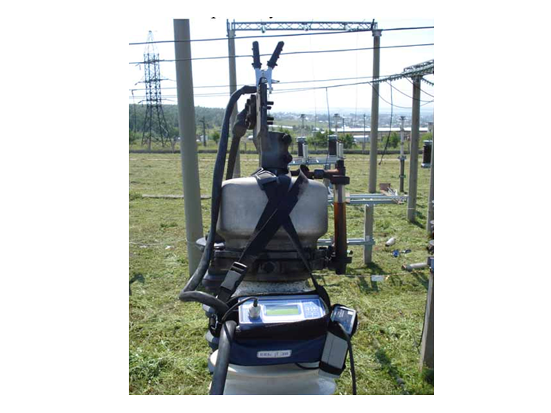
Thanks to light weight of the MIKO-2.3 the measurements can be performed with the instrument placed on the circuit breaker cover or on the servicing platform of a lifter. You can use short cables, which is of importance, taking into account their large cross-section and heavy weight. Despite the fact that the instrument is furnished with a cable of the K162 microohmmeter for operation on the 6÷110kV circuit breakers, you can select a shorter and lighter (K161) or a longer (K163…K165) cable depending on the voltages of circuit breakers available.
1.1. Prior to climbing a circuit breaker, turn it to ON position and earth one terminal of each pole. DO NOT unearth the input and DO NOT change the circuit breaker into OFF position during the entire period of operation.
1.2. If a circuit breaker has no built-in current transformers (CT), it is more convenient to operate the instrument in the self-powered mode without connection of a charger. A fully charged battery allows at least 20 measurements at 950-500A current, which is sufficient for testing all the three poles of a circuit breaker. The battery shall be charged prior to climbing the circuit breaker. For that purpose, without withdrawing the instrument from the bag, unfasten the flap at the bag bottom and plug in a short cable of a charger into "Charging" socket, turn the instrument on and wait until the charge level is 100%. Now you can disconnect and switch off the instrument.
1.3. For bulk-oil circuit breakers with a built-in transformer the instrument should be powered from mains via a charger that is fastened to a bag.
1.4. To perform measurements in Mode 2 on all the three inputs of a circuit breaker from one battery charged on the ground, you can change over to Input 3 only after the DISCHARGE message appears on the screen. In this case Е=(20÷23)% and the remaining charge will be sufficient for making measurements on the third input. If you do not wait until Е=(10÷15)%, then at the third input the instrument will require recharging, and an extension wire from the ground will be needed.
1.5. To perform measurements in Mode 2 on all the three inputs of a circuit breaker from one battery charged on the ground, you can change over to Input 3 only after the DISCHARGE message appears on the screen. In this case Е=(20÷23)% and the remaining charge will be sufficient for making measurements on the third input. If you do not wait until Е=(10÷15)%, then at the third input the instrument will require recharging, and an extension wire from the ground will be needed.
1.6. During operation from a lifter platform a long section of the cable is connected first, then a lifter is installed against the second input and a short section of a cable is connected to it. So that not to drop the second part of a cable during lifter motion, tie up a rope to the short section of a cable and fasten its second end to the lifter platform. This rope is used for raising the second section of a cable.
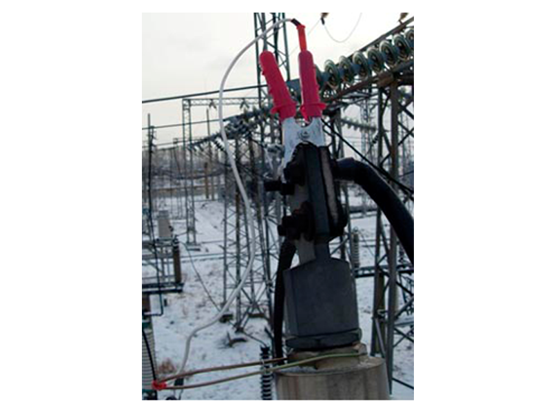
1.7. Connect the ends of the measurement cable to terminals using clamps; make sure that all the teeth of the current contacts are in close contact with the input electrode surface. Now tighten the nut of a G-cramp.
1.8. Plug in the microohmmeter test cable into the INPUT II outlet socket via the lateral restriction cramp such that the white mark on the power plug surface faced the side wall of the instrument.
1.9. Open a side flap of the bag and securely tighten the screw head.
1.10. Plug in the microohmmeler cable into INPUT 1.
1.11. Connect the charger following guidelines in Item 1.2. The instrument is ready for making measurements.
1.12. In a cold season a charger and a cable should be preliminarily connected in a warm room. Pay special attention to screw tightening (Item 1.8).
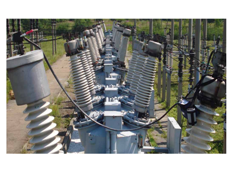
In a power circuit along with the transient resistance of contacts there are some other types of resistances: in the bolted joints of terminals with conductor wires; in the bolted and threaded joints of terminals with input pins; in the bolted joints of arch extinction chambers.
When the MIKO-2.3 terminals join the current and potential contacts, it automatically forms a four-wire diagram. But only transient resistances between unit terminals and leads are eliminated when they are connected to unit terminals. Transient resistances of other fixed joints remain.
Transient resistances between unit terminals and input pins can be eliminated from the results of contacts transient resistance measurements by using external spring-loaded or pin-type potential contacts.
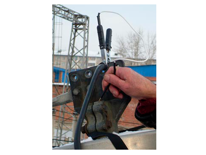
When a plug of an external potential contact (EPC) is inserted into a socket built-in into a crocodile clip hand, a potential from EPC enters the instrument, rather than a potential from a fixed potential crocodile contact. Measured is the resistance on the section between two EPCs rather than on the section between 'crocodiles'.
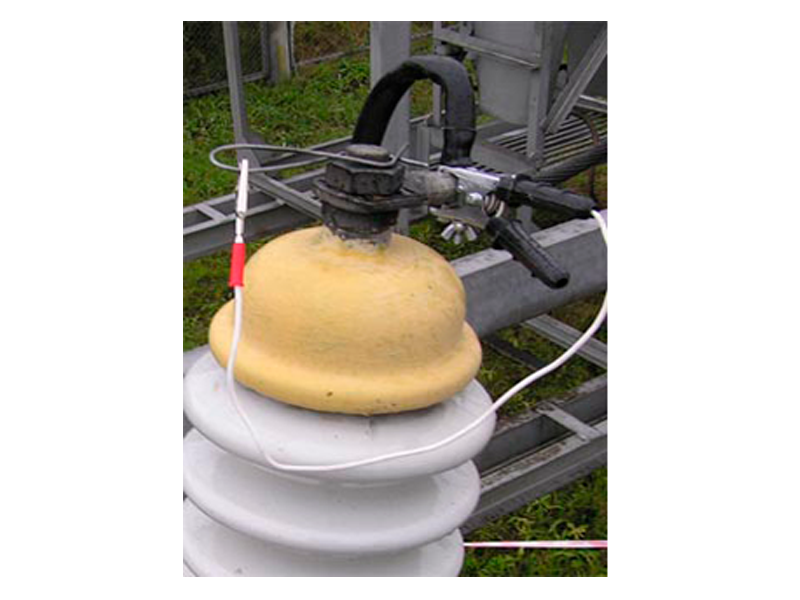
Fig. 3 shows a spring-loaded potential contact mounted on the input pin of the C-35 circuit breaker. After placing the spring-loaded potential contact on the pin, turn it right-left for cleaning the pin surface in the area it touches the teeth of a spring-loaded potential contact. The spring-loaded potential contact can be mounted on the pin with a unit terminal (Fig. 4) in a similar way.
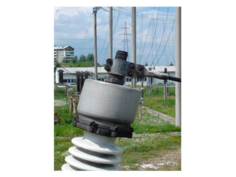
If a unit terminal completely covers the pin (Fig. 5), the spring-loaded potential contact is mounted on the top nut of an oil expander. There is always a small gap between this nut and a safety nut of a unit terminal located above. For this reason the test current does not flow across the nut of an oil expander and nut's potential is equal to that of a pin.
With the unit terminals where only the pin bottom is accessible, pin potential contacts are used that are to be held by hands (Fig. 6) after cleaning the oxidized surface of the bottom using a sharp end of a contact. In some unit terminals a steel bolt was screwed up into pin bottoms many years ago and became rusty. It is not worth while pressing a pin contact against it as the best contact is formed with a pin made of copper alloy.
When a pin-type contact is used on the 110kV (and above) circuit breakers, two persons are needed due to a long distance between inputs. On the 35kV circuit breakers (and less) both contacts can be held by one person if he uses a startup delay mode.
For measurements on an arch extinction chamber the K121 potential cable may be more appropriate than external potential contacts with short cables described above. The cable has two 1.8m wires (upon order the length can be extended) terminated with plugs for placing either a small crocodile clip or a pointed probe. Cable socket is inserted into INPUT 1 of the instrument instead of microohmmeter cable socket (К161…К165).
If connection using 'crocodile' clips is not possible, the cables with pin-type current and potential contacts K154 and K155 should be used. The potential pin-type contact must be spring-loaded. Startup delay mode in this case allows the instrument to be operated by one person only.