 Русский
 Français
 Chinese
Detection of transformers malfunctions by using MIKO-2.3 and PKR-2(M) instruments
Power transformers are one of the most widespread and significant elements of power systems. It is natural that the reliability of grids, power plants and power systems depends to a large extent on the reliability of transformers, especially since a significant number of transformers have already exceeded the minimum service life of 25 years stipulated by the standard.
The most severe damage to the transformer is an internal short circuit (SC). Internal short circuits can occur both when switching devices are damaged and when windings are damaged.
Up to 40% of the total number of catastrophic transformer failures are related to damage to on-load tap changers (OLTC).
By design, OLTC is a complex and often insufficiently reliable component of a power transformer. Timely detection of upcoming defects with such importance of OLTC for the transformer as a whole is necessary by carrying out preventive measures depending on the OLTC condition. This requires frequent monitoring during operation.
A preliminary assessment of the condition of the contacts is made by measuring the ohmic resistance of the entire transformer winding by supplying direct current when the OLTC occupies various positions. This procedure detects internal short circuits and increased resistance of the OLTC contacts. To measure the ohmic resistance of the transformer windings, it is recommended to use the MIKO-2.3 instrument (Fig. 1). In this case, in the "milliohmmeter" mode. The instrument allows measuring resistances at all transformer taps relatively quickly.
To directly determine the deterioration of the OLTC, it is necessary to measure the contact resistances. Overheating and erosion of contacts cause an increase in the initial value of the contact resistance several (or even dozens of) times.
To measure the contact resistance of switching devices, you can also use the MIKO-2.3 instrument, which allows you to perform measurements at any (from 100 to 750 A) current you set with an error of only 0.2%. In this case, the instrument is used in the "microohmmeter" mode. The initial value of the resistance of the OLTC contacts to be opened is usually 40-200 μΩ. An increase in the contact resistance 3-4 times may be a sign of a defect, after which an avalanche-like increase in resistance can be expected. At this stage, the state of the contacts can be improved by repeated switching. An increase in the contact resistance 5-10 times may be due to irreversible erosion of surfaces, and special mechanical treatment or replacement of contacts is required to restore the normal state.
Reasons that increase the resistance of circuit elements can be:


- weak contact pressure;
- burning of contactor contacts;
- burning of the selector contacts due to "dangling" of the movable contacts or prolonged operation in the same position (Fig. 2);
- poor tightening of bolted connections or poor pressing of pressed tap contacts.
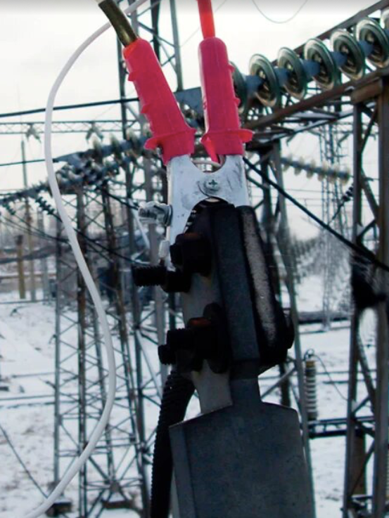
Recording the circular diagrams is a mandatory procedure during acceptance, after repair, and during inspection of the OLTC. Recording the actuation moments compared with recording the angle of shaft rotation helps understand the relative position of the contacts and their deviation from the previously obtained diagram. Oscillography of the switching process allows you to detect delayed actuation, non-simultaneous actuation by phases, repeated contact actuation. Using PKR-2(M), it is possible to record the oscillogram and circular diagram simultaneously for three phases of transformer without using additional devices (for example, resistors) (Fig. 3).
By recording the circular diagram of the action sequence of the contacts of the selector and contactor during forward and reverse travel, you can judge the quality of the selector assembly by the backlash value. Then ten switching cycles are performed, and if there are no defects, it is considered that the switching device is repaired satisfactorily.
When analyzing the circular diagram, special attention is paid to the value of the overlap angle α (Fig. 4) between the contactor and the selector, i.e. from the moment of opening the arc extinguish contacts of the contactor to the moment of opening the contacts of the I1 and I2 selectors. For example, for a RNT-20 device, this angle must be at least 20°. If the angle α is less than 20°, its value can be adjusted by the vernier coupling of the horizontal shaft located inside the transformer. Inconsistency in the operation of the switching device must be eliminated in order to avoid damage to individual elements of the OLTC.
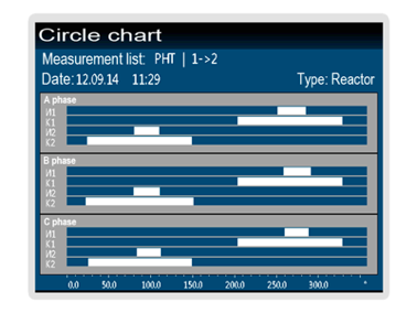
Fig. 4. A circular diagram of the LTC reactor recorded by the PKR-2 instrument across three phases
MIKO-2.3 and PKR-2(M) allow not only to get reliable data about transformers, but also to do it much faster than their competitors.