 Русский
 Français
 Chinese
Method for the contact resistance measurement by using the MIKO-1 instrument
- Connect the current ends (with "crocodiles") of the MIKO-1 cable to high-voltage leads (1 and 2), and the potential ends (needle-type) – to high-voltage lead-ins of the upper cover flange 3 and the intermediate flange 4 (Fig. 1). If the contacts of the circuit breaker are of socket type, and the measured contact resistance exceeds the rated value, perform mechanical break operations 5-10 times and repeat the measurement. If the resistance is still higher than normal, the circuit breaker must be repaired.
- Measure the contact resistance directly on the high-voltage lead-in 1 and the tie plate 2 (Fig. 2).
- Measure the contact resistance on the tie plate 2 and the load lead-in 3 (Fig. 2).
- Measure the contact resistance directly from the load terminal 3 to the high-voltage wire 4 (Fig. 2).

Fig. 1
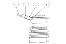
Fig. 2
If the contact resistances measured according to clauses 2, 3, 4 exceed the rating for this circuit breaker, disassemble the connection, clean, and lubricate the contact surfaces according to the instructions of the circuit breaker manufacturer.