 Русский
 Français
 Chinese
Detection of faults in the reactor devices of LTC by recording circular diagrams
Electric network voltage is one of the parameters determining the quality of power supply to consumers that is maintained with the help of control devices of power transformers and autotransformers. According to the operating principle they are divided into off-circuit switches, and LTCs. All the switches are an inherent part of power transformers, and their main objective is to ensure long-term failure-free operation of transformers. The scope of switching devices tested during commissioning must conform requirements of RTM 16.800.723-80 and manufacturer's guidelines.
According to codes, LPC tests shall mandatorily include test of the switching device contactor operation sequence versus the angle of shaft drive turn, in other words, circular diagram recording. The principles of reactor switches operation are to a great extent similar, therefore, we will consider a standard diagram of a properly operating reactor device of LTC of RNT-20 type (Fig. 1), and some requirements whose violation causes failures that need control (Table 1).
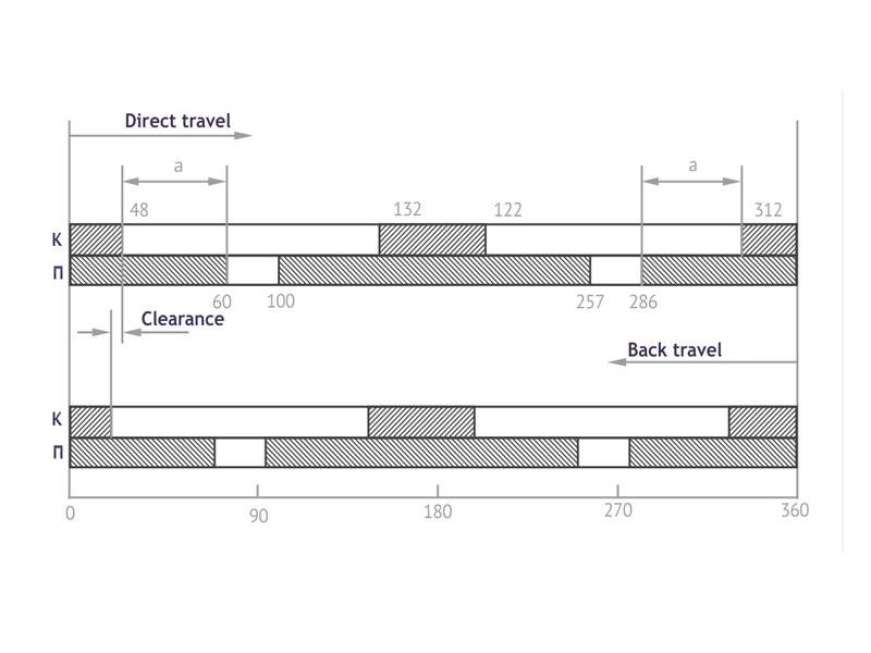
Table 1. Requirements to a circular diagram of LTC device of RNT-20 type and methods of control in case of their violation
|
Requirements |
Methods of deviations control |
|
Contact overlapping angle; "а" should be ≥ 30˚ |
Adjustment of a horizontal shaft of the switch inside a transformer is needed |
|
Clearance (displacement between "direct" and "revers" switch travel) shall not exceed the one indicated in manufacturer's guidelines |
Check the adequacy of assembly or replace worn-out details of a switching devices or those whose service life expired |
|
A developed diagram is not symmetrical with respect to 180о angle, |
A vertical shaft connecting a drive mechanism with a contactor box needs adjustment |
|
An interval expressed in vertical shaft rotation angles during which the contactor is closed, shall be symmetric about the interval during which the switch is closed. |
|
At present the circular diagrams are recorded using obsolete methods and tools. They include, for example, "warning lamps", amperemeters and voltmeters, discs with a circular scale for measuring the shaft rotation angle. They are rather costly and take time for assembly of electric circuits and for calculations; they do not ensure detailed LTC analysis.
It is more appropriate to use a modern instrument for transformer LTC diagnosis – PKR-2 (the latest version of the PKR-2M) manufactured by SKB EP that is designed for testing the state of voltage control devices of reactor and resistor type within the power transformer and outside it.
The PKR-2 (PKR-2M) allows circular diagram recording in conformity with the main requirements, and the instrument demonstrates the results of diagnosis of an operable (Fig. 2) or failed (Fig. 3) LTC device. For graphic or tabular presentation of data the PKR-2 (PKR-2M) is furnished with a color graphic display that facilitates the graph interpretation. Moreover, it is supplied with PC software that allows more detailed analysis of results obtained by the instrument and documentation of reports based on the results of tests.
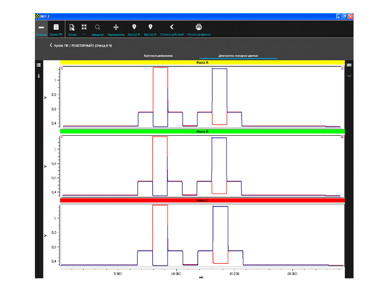
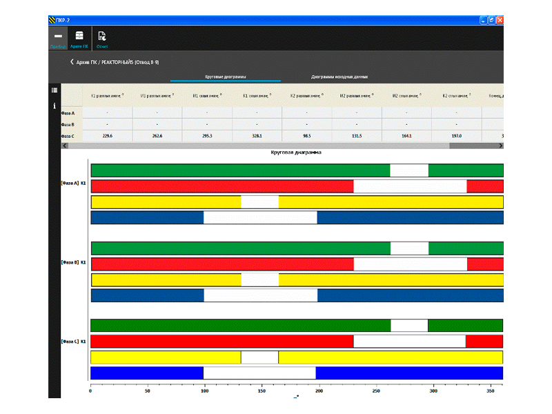
Fig. 2. A circular diagram of a properly operating LTC device of RNT-20 type using the PKR-2 instrument (results view with the help of the PC software)
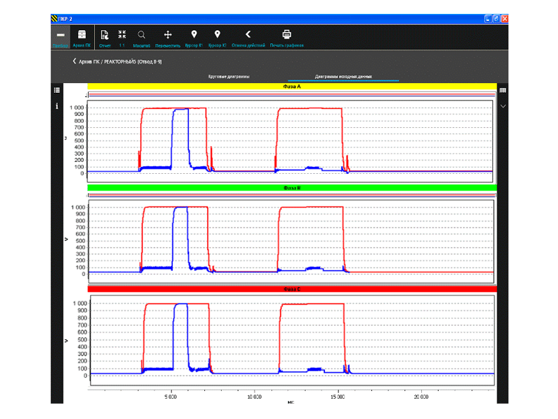
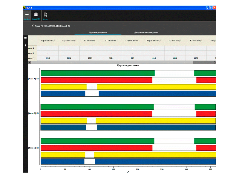
Fig. 3. A circular diagram of a properly a faulty LTC device of RNT-20 type using the PKR-2 instrument (results view with the help of the PC software)
The PKR-2 allows both the circular diagram recording and provides additional information on LTC operability/fault, including information on incorrect assembly of the switching device. Let us consider data given in Fig. 3 as an example.
After the overhaul pf LTC of RNT-20 type it was assembled erroneously. The LTC contacts switch-over (measuring the test current value) were subjected to control using the PKR-2 instrument that detected incorrect connection of a lead of one of the halves of LTC reactor. Instead of connecting it to the main contact it was connected to a middle point where a zero wire or an exciting winding was to be connected (Fig. 4).
Under the lack of present-day diagnosis devices, at the moment of LTC switchover this error may lead to failure of transformer operation and thus deteriorate the equipment operation safety.
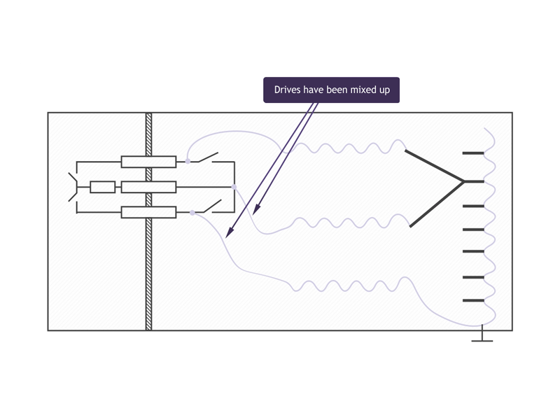
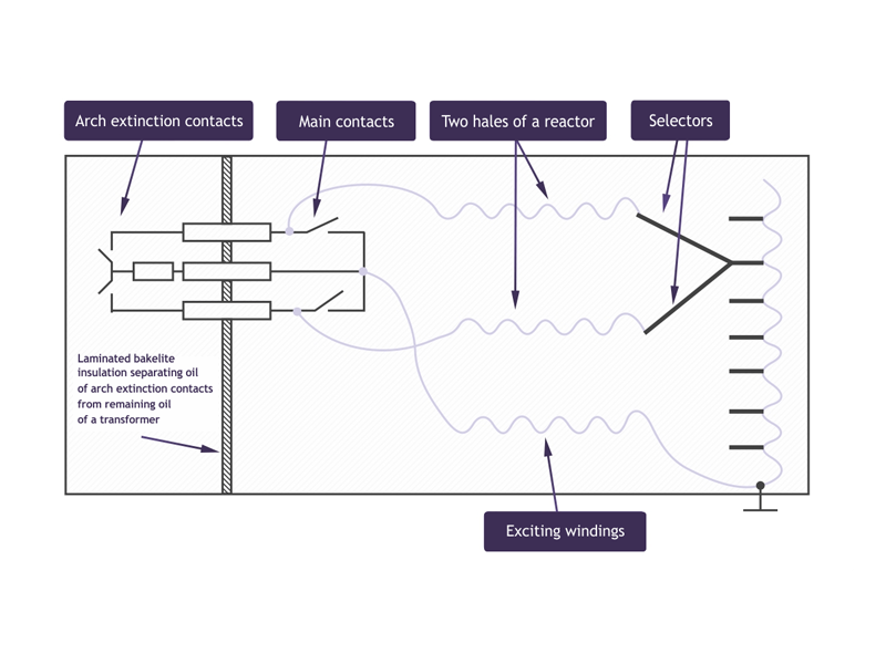
Fig. 4. A diagram of correct and incorrect connection of transformer windings with LTC of RNT-20 type
Use of the PKR-20 considerably reduces expenses and labor costs of the company, raises the transformer diagnosis quality, eliminates unnecessary repair owing to early faults detection:
- The PKR-2 (PKR-2M) allows recording the circular diagram (for reactor and resistor LTC) and oscillograms of contactors operation (fast LTC of resistor type) across all the phases at a time in one switchover from one lead to the other;
- Connection of additional external accessories (couplers or resistors) is not required. It is automatically adjusted to a particular LTC;
- For recording the circular diagrams the instrument is furnished with a high-precision angle displacement transducer, and a special fixing method considerably reduces the error of rotation angle measurement that may be caused by possible shaft, axis and plugs eccentricity. It is installed without using any special tools, it is simply seated on the shaft extension;
- The main peculiarity of the PKR-2 is a unique, specially developed integrated method for transformer LTC devices testing that has no analogues.
The PKR-2 design takes into account all the merits of the PKR-1 that have been highly appraised by the SKB EP equipment users. Thus, the PKR-2 combines merits of its forerunner and acquired new advanced capabilities. The result is a device that is highly efficient for control and diagnosis of LTC devices of reactor and resistor type.