 Русский
 Français
 Chinese
The MIKO-8 milliohmmeter with a function of non-destructive testing of the transformer LTC condition
It is a high-precision instrument for measuring the winding resistance of any electric equipment and for non-destructive control of transformer LTC.
Milliohmmeter mode
- The measurement algorithm eliminates division of the entire range into several subranges, thus eliminating a high error when measuring at the start of each subrange scale, which is mandatory in all the milliohmmeters available at the market. The only measurement range in the MIKO-8 is from 10 mkOhm to 10 kOhm, and across the entire range from 500 mkOhm to 10 kOhm the error does not exceed 0.1%.
- The instrument has higher output power (up to 62W) that allows higher friendly signal (voltage drop on the active winding resistance) and reduction of a noise signal owing to lower reactance of a winding due to strong magnetization. Output power can be adjusted within different limits, up to 0.3W, which eliminates winding heating by the test current even in low-capacity equipment, for example, in current transformers. In case of erroneous setting of the excessive power causing the winding heating and increase in its resistance, the display shows the symbol that warns that power shall be lowered.
- Automatic setting of the optimum test current value throughout the entire range of resistances and automatic stop at the end of measurements facilitates the instrument operation and eliminates subjective error caused by instability of the measurement process.
- For rapid measurement across several (or all) winding leads there is a LTC mode when the test current is stabilized on the very first lead and is tripped only after the measurements are performed on the last lead.
- The MIKO-8 (along with the MIKO-7) is the only milliohmmeter with a number of automated operations (after termination of the three-phase winding resistance measurement), namely:
- computation of differences in resistances between phases;
- conversion of linear resistances into phase ones;
- reduction of measured resistances to reference temperature;
- computation of deviation of measured resistance from the reference value;
- computation of current winding temperature.
- Power supply from an external battery (for example, from a car battery) allows instrument use on substations under construction under the absence of a ≈220W network, and raises instrument mobility for its use at operating substations.
- For data presentation in the graph or tabular form the instrument has a large color display of high brightness and contrast that makes it readable even on a sunny day.
These functions eliminate errors of manual conversion and save time of transformer testing.
A mode for non-destructive testing of LTC
This mode facilitates obtaining the information on condition of LTC with current-limiting resistors. Only if the fault is detected, you will have to open the contactor tank or withdraw a unit from the transformer tank for detailed examination using special-purpose PKR-1 or PKR-2 devices and for subsequent repair. Non-destructive testing can be performed both prior to measurements in the milliohmmeter mode, and after it.
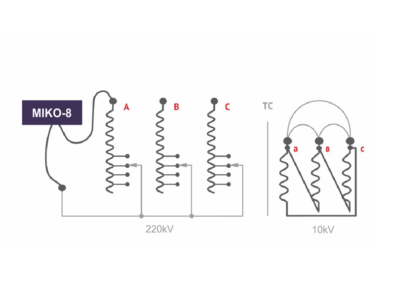
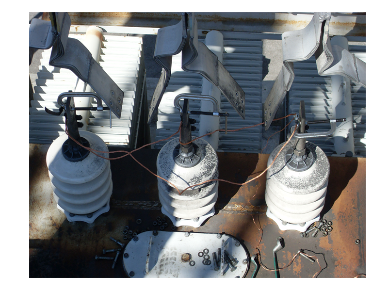
Non-destructive testing procedure is based on the DRM-method (direct resistance measurement) and consists in measuring the current value via the winding connected to LTC during its switch-over from a lead to a lead. Constant voltage is supplied from the MIKO-8 output to the input of an indicated winding, and secondary transformer windings are short-circuited (Figs. 1 & 2).
Owing to the secondary winding short-circuiting the current in the circuit can be measured quickly by responding to rapid changes in the circuit resistance during contacts switch-over. Fig. 3(a) shows an oscillogram of current during LTC switch-over across all the leads, first in the direction of winding resistance reduction then in the opposite direction.
Each step of current change on the oscillogram reflects selector switch-over to the next lead. The step value is determined by a sum of the following resistances: winding resistance on the lead, selector and contactor contacts resistance. Short pulses between adjacent steps are a consequence of current-limiting resistors switch-over by a contactor. A close-up picture of one of such pulses is given in Fig. 3b. It looks like an oscillogram of contactor switch-over that is distorted by the winding inductance.
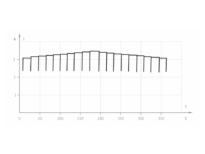
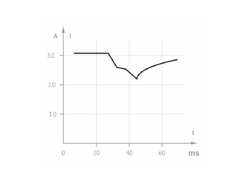
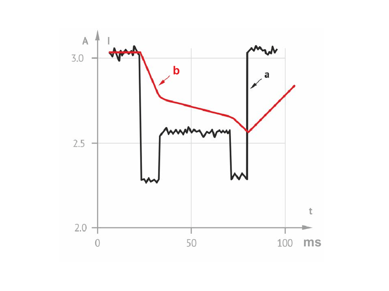
Fig. 4 shows two overlapped oscillograms of contactor switch-over: (a) an oscillograms obtained directly on the contacts at removed cover of the contactor tank; (b) an oscillograms obtained using non-destructive method via transformer inputs.
Points of the main and arch-extinction contacts switchover, and integrity of current-limiting resistors are very well seen on the oscillogram (b) despite its smoothness These points coincide in time with similar points of the oscillogram (a).
While commuting from one lead to the other, the test current fails to fully stabilize and its measurement yields a higher error than at static measurements in the mode of milliohmmeter. But DRM-method gives additional information on the defects in LTC. For example, in the PC, PHOA, etc. devices one can identify adequacy of the main and arch-extinction contacts operation, their condition (burnt or non-burnt contact), and integrity of current-limiting resistors. In devices of PHTA-35/320 type and in similar devices where a contactor and a selector are replaced by fine adjustment switch, you may check the main and arch-extinction contacts, a current-limiting resistor, as well as condition of surfaces of all the fixed contacts through which the moving contacts move. Measurements in the milliohmmeter mode and in the mode of non-destructive test supplement one another, and give a more detailed picture of the transformer condition.
Fig. 5 shows a photo of the MIKO-8 display with a standard graph of current value measurement at the moment of a properly operating LTC contactor switchover. The most typical sections of the graph are noted by arrows and commented. Using the keys you may install two cursors on the indicated points and measure time of switch-over and current values at those moments, as well as difference between time and current values.
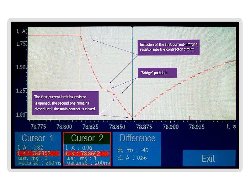
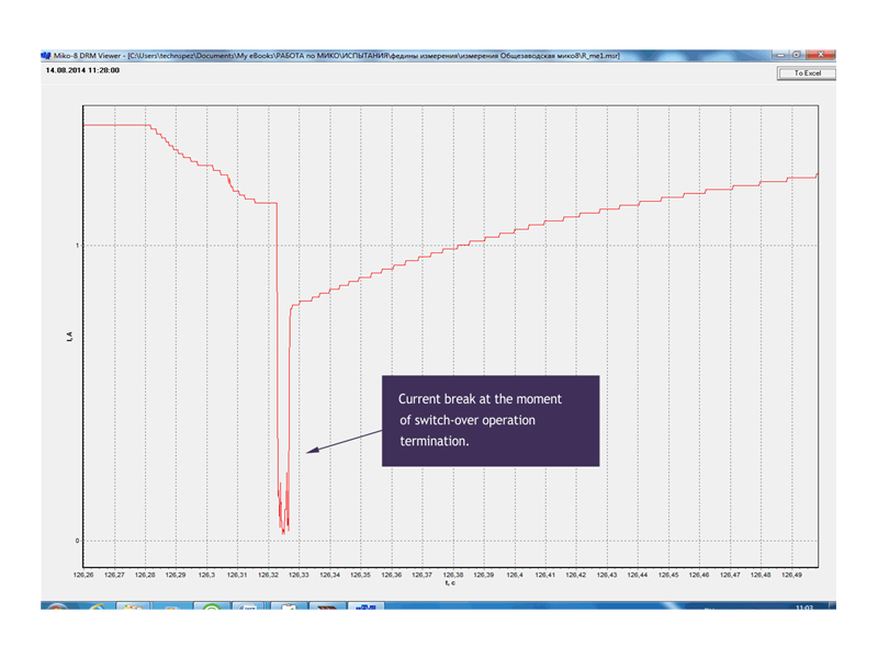
Fig. 6 shows a photo of a current graph of a faulty LTC that is displayed by a data viewer program of MIKO-8 on the PC display. Current interruption of approximately 5 ms that occurred at the moment of switch-over termination is very well seen on the graph.
Since current was interrupted at the moment of switch-over from an odd to even lead (at the moment of switch-over from an even to an odd branch the current was not interrupted), then current interruption may cause rebound of one of moving contacts.
For RNTA-35/320 devices the switch-over oscillogram shall be analyzed on all the leads (Fig. 3), rather than on one lead only (Figs. 5&6). The second oscillogram can show defects in the fixed contacts: oxidized or coaled sections of contacts with higher resistance, up to complete break. On the graph these sections are located on the steps between moving contacts switch-over from one lead to the other.
Since non-destructive testing of LTC condition is a rather simple, cost-effective procedure that does not require deep knowledge of LTC design, and its operability evaluation criteria are rather simple (for example, lack of current interruption for more than 5 ms), this testing procedure can be recommended for all the scheduled and off-schedule tests of power transformers.