 Русский
 Français
 Chinese
Testing the condition of selector contacts in LTC devices of RS-3, RS-4, and RS-9 type using the MIKO-8 milliohmmeter
Power transformer operability depends on the proper operation of switched-over contacts and bolted current-carrying connections. With time the loaded springs of contacts lose their power, and in the conditions of permanent vibration and under the impact of magnetic fields the bolted joints tend to unscrew. Reduction in the spring power and slackening of the bolted joints results in the transient resistance increase, in heating and subsequent burn-off of the joined details.
Chromatography analysis of oil is one of the methods of transformer condition control. According to RD 153-34.0-46.302-00 [1] this method allows detection of a number of defects (by groups): overheating of current carrying joints and structural elements, and electric discharges in the oil. This method allows detection of overheating presence, but not its location.
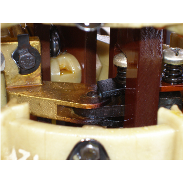
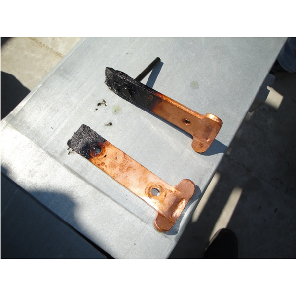
The second method of non-destructive control of connections is testing the temperature distribution using a thermal imager. According to RD 153-34.0-20.363-99 [2], a contactor tank contains a small amount of oil, therefore, heating of its contacts can be detected by a thermal imager. Results of measuring the overheating degree of switch contacts (selector contacts) are often incorrect due to natural heat flows and oil circulation, which hamper detection of some faults (Figs. 1 and 2).
The third method of testing the state of LTC contacts consists in measurements of DC resistance of transformer windings between "phase-to-zero" or "phase-to-phase" inputs, which is mandatory at any maintenance. The fact that relative difference of winding resistances (contact connections) does not exceed 2% is assumed to be the criteria of the lack of defects.
For sensitivity evaluation of the third method let us consider an example: the TRDN-40000/110 transformer with HV winding with a 'star' connection diagram and LTC mounted on a zero phase.
"Phase-to-zero" resistance of winding of the TRDN-40000/110 ≈ 1.0 Ohm, i.e., 2 % of resistance makes 0.02 Ohm. According to [3], reference resistance of selector contacts makes about 20 × 10-6 Ohm. Thus, measurement of "phase-to-zero" resistance of winding allows detection of change in the selector contact resistance that differs from the norm 1000 times. It is this method of control that allows detection of faulty contacts of a commuted device.
For raising the sensitivity of the third method of testing we recommend the following sequence of actions: open the LTC contactor and perform additional measurements of resistances, for example, using the MIKO-8 (Fig. 3).
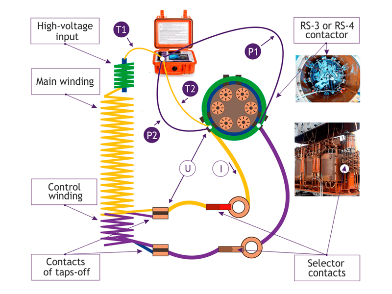
Fig. 3. A digram of MIKO-8 connection for testing the condition of selector contacts on one of the phases:
T1 and T2 are current measurement circuits; P1 and P2 are potential measurement circuits;
U is measured voltage drop; I is electric current flow direction.
The main difference from the conventional approach is that the test current of the instrument is supplied to the contactor contacts (e.g., contact X31 of Phase A) and is released from the appropriate transformer input. This type of current feed allows magnetizing the magnet system of a transformer and thus reduces its impact on the results of measurements.
For preventing the voltage drop on the selector contact that is created by test current of the MIKO-8, one of potential clamps of a test lead is connected to the X31 clamp, the second one - to the X32 contact. With such a connection one of the potential cables is continued by a circuit: "a cable connecting a contactor with a selector - selector contact - transformer tap-off - a part of a control winding of the transformer." The MIKO-8 milliohmmeter has high resistance of a potential input, therefore, resistance of this circuit has no impact on the measurement accuracy.
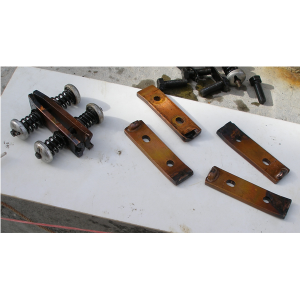
Accurate value of measured resistance is very often unknown, for this reason an issue of the criteria for making a decision on the tested contacts operability arises. According to Fig. 3, the measured circuit includes resistance of cables that connect a selector with a contactor and transformer winding. According to Fig. 4, the length of cables connecting the selector contacts with winding of each phase is different. Therefore, it is not correct to compare the results of resistances measurement between phases. On the other hand, simultaneous failure of two moving contacts of a selector (even and odd ones) on one phase is a rather rare phenomenon, therefore, in this case it is necessary to compare the DC electric resistance of the odd and even LTC leads for each phase separately.
For evaluating the sensitivity of the proposed method the length of a cable (l), connecting the selector contact with a transformer winding was 5 m (maximum). The rated current of HV (I) winding whose sensitivity value at 'phase-to-zero' resistance was measured, was as high as 200A. Current density (∆) a copper winding of the oil transformer was 4.5 А/mm2 [4]. a copper winding of the oil transformer was (S) – 44 mm2 (1).
S = I/∆ (1)
Specific copper resistance (ρ) is 0,018 Ohm*mm2/m. Conductor resistance, according to the Ohm law, is calculated using the formula:
R=ρ× l/S (2)
By substituting the appropriate values into formula (2) we get the following result: 5m cable resistance for the selected transformer makes 2 mohm; 2% of the value obtained makes 40 mkOhm. Hence, at testing the LTV selector contacts condition the method sensitivity is commensurable with reference values of properly operating contacts.
The considered procedure can be performed using the "amperemeter - voltmeter" method but it will be more labor-intensive, therefore, it is more advisable to use a milliohmmeter (ohmmeter).
When choosing between a milliohmmeter and the described method of measurements the following facts should be taken into account:
- The considered example of the resistance measurement lies within the range of microohmmeter control. Such instruments are available at the market but they are mainly intended for measuring the transient resistance of contacts and cannot be used for measurements following the above procedure as they are not designed for measuring the inductance circuits;
- The lower limit of the instrument's measurements range shall begin with 10 mkOhm;
- For accurate determination of the condition of tested contacts the error of measurements shall not exceed 0.5 %;
- For reducing the impact of self-inductance voltage on the results of measurements (it induces 'noise' voltage on potential measurements circuits) the test current flowing through the transformer windings must be stable;
- For reducing the time of measurements, i.e., to accelerate the transformer core re-magnetizing the milliohmmeter must generate sufficiently high test current and have high output power.

The MIKO-8 milliohmmeter meets all the above requirements, and the proposed procedure was tested on site.
The instrument measures the electrical DC resistance of the windings of transformers, current transformers, electromagnets and electric motors; Compensatory, current-limiting and other resistors of high-voltage circuit breakers; Contacts and contact connections of power and signal circuits; Cables.
- The range of measurements is 10 мmkOhm ÷ 10 kOhm.
- Maximum allowable error of resistance measurement does not exceed ±0.1%.
- Highly stable test current of up to 10A.
- It ensures accurate measurement of low and high resistances by adjusting the instrument output power within 0.3Vt ÷ 62Vt.
REFERENCES:
1. RD 153-34.0-46.302-00. Methodological guidelines on early detection of transformer defects based on the results of chromatography analysis of gases dissolved in oil. Validated on 01.01.2001.
2. RD 153-34.0-20.363-99. Main principles and infrared-based diagnosis of electric equipment and power lines. Validated on 01.06.2000.
3. Yakobson I.A. Adjustment of high-speed switches of power transformers. Moscow, Energiya Publishers, 1967. 96p. (incl. figures). (Manuals for electricians. Issue 433).
4. Tikhomirov P.M. Transformer design. Text book. 4th issue, revised. Moscow, Energiya Publishers, 1976, 544p. (incl. figures).