Dependence of the contact resistance change on the moment of contact compression force
Translated from Russian
Various connections of electrical contacts have a contact resistance that depends on many factors, for example, compression ratio, material or temperature. The contact resistance value itself is an important parameter in any electrical installation, so it is normalized and checked since its increase leads to disruption of operation in the power system and emergency, and sometimes even life-threatening situations.
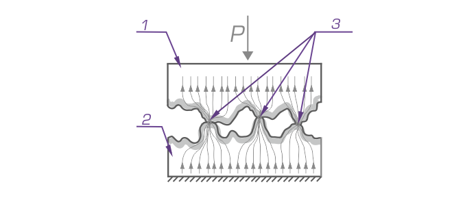
The contact surfaces have microscopic elevations and depressions, as a result of which their contact does not occur over the entire area, but only at individual points, which are called contact points (Fig. 1). At points with a strongly diminished cross-section, the current from one contact surface passes to another resulting in high electrical resistance, which is called contact.

Figure 1. Contact of two mating surfaces
1 and 2 - mating surfaces, 3 - contact points
The contact resistance mainly depends on the state of the contact surfaces and pressure with which the contacts are pressed against each other. In contacts that do not experience pressure (forces pressing the contacts to each other), the number of contact points is insignificant. As the pressure on contact surfaces increases, the projecting irregularities become deformed, and the initial points of contact turn into small areas.
Dependence of the contact resistance on the pressure of contacts on each other is explained by the fact that at high pressure it is easier to crumple the points projecting on their surface and thus, improve the contacts between them. At the same time, new contact points are created on mating surfaces to improve the conditions of current transition, and, consequently, the quality of contact.
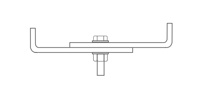
To prove the above data, an experiment was carried out on two aluminium buses 10 x 100 mm (M16 bolts) which were compressed with torque wrench (Fig. 2).

Figure 2. Aluminum buses and their connection
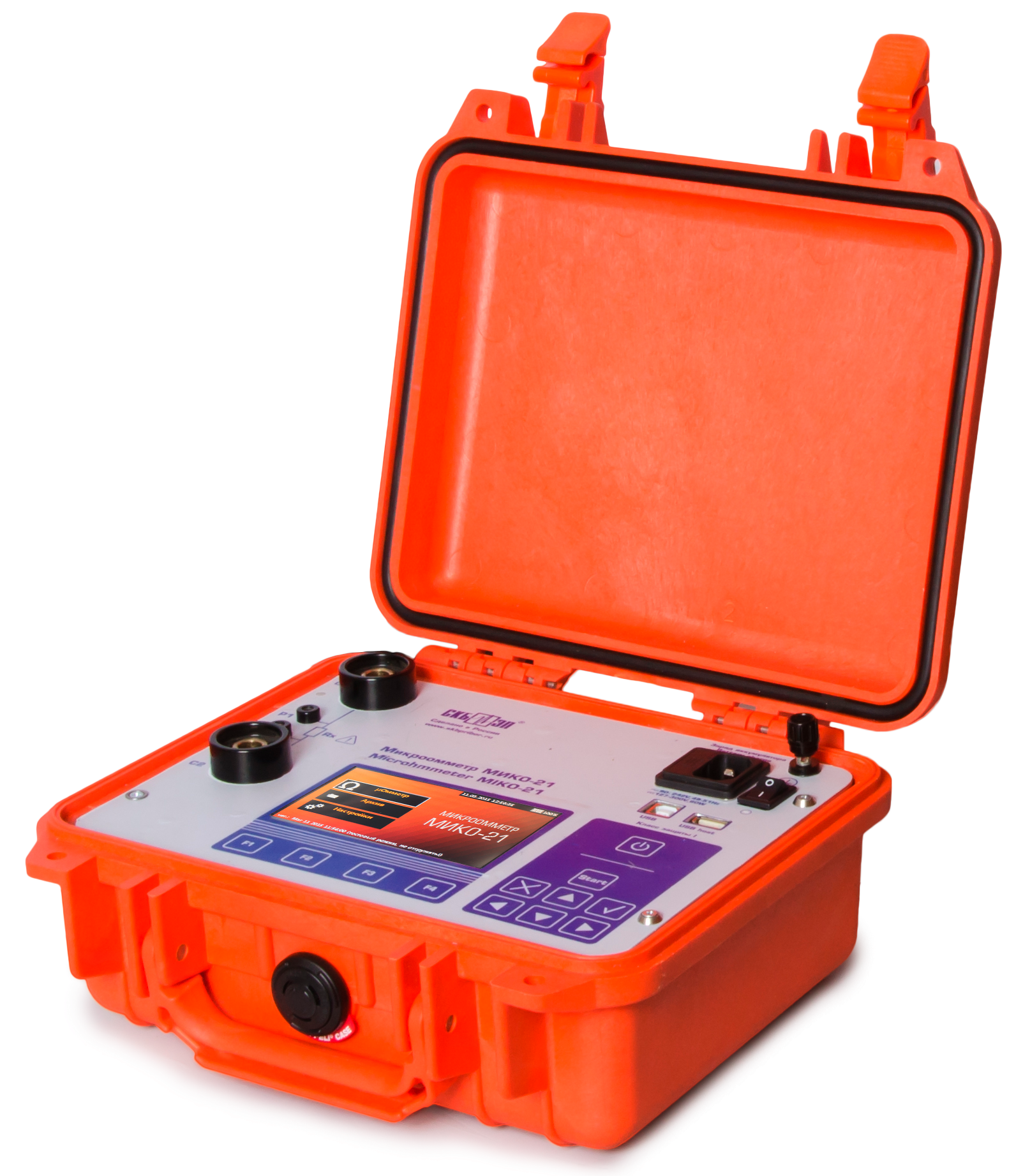
For this evidence - based experiment, a high precision micro-ohmmeter MIKO-21 manufactured by SKB EP LLC was selected, which has an obvious advantage over its analogues with better combination of functionality in view of the Users needs.
MIKO-21 is designed to measure contact resistances of the electrical equipment circuits in the range of 0.1 μΩ - 2 Ω under operating current of up to 200 A with the lowest error of ±0.05% among similar devices (Fig. 3).

Figure 3. MIKO-21 micro-ohmmeter
Contact area of the two aluminum plates was previously cleaned, since the result of the contact resistance greatly depends on the treatment of the contact surfaces and their condition, and the compression ratio was carried out according to VSN 164-82.
According to the VSN 164-82 "Design and Installation Guidelines to Busways-to-Busway Contact Connections and Connections of Busways to Utilization Equipment Leads" and paragraph 7.12. - it is necessary to tighten the bolts of contact connections with indicator wrenches having the following torque:
| Bolt diameter |
M10 |
M12 | М16 | М20 |
| Torque, N × m | 40-50 | 60-70 | 90-100 | 120-130 |
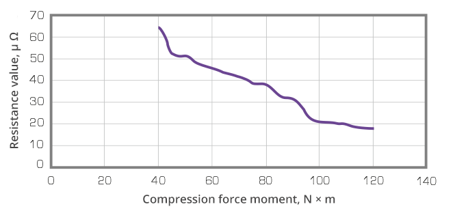
All measurements were made with current of 200 A. Increment of increasing the moment of compression force was 5 N*m with an initial value of 40 N*m. Graph 1 shows that with increase in the compression force moment, data of the measured contact resistance decreases, but when the moment of compression force reaches more than 100 N*m, the reduction rate slows down.

Graph 1. Dependence of the contact resistance change on moment of the contact compression force
The greater the number and area of contact points between the contact surfaces, the lower the contact resistance between them. However, intensity of process of the new contact points formation gradually slows down even with further rise of pressure in the contacts. This is explained by the fact that when the pressure increases, it is perceived by a larger area, specific pressure at the contact points decreases, the contact material is crushed less intensively, so the process of increasing the number and area of contact points decelerates.
The contact resistance is the main indicator of quality of any contact and largely depends on the treatment of the contact surfaces and their condition. Of course, the moment of compression force exactly as the contact resistance indicators have their own norms, which shall be complied with because even a minimal excessive compressive force may lead to deformation of the contact and the fastening material, which will worsen the contact resistance.
When it comes to devices for measuring the contact resistance, you should opt for equipment that meets following criteria:
- Device test current shall be close to the operating current of the tested object, since the oxide film and non-metallic inclusions cause an increased contact resistance (hereinafter referred to as Rcon.), which goes down with an increase in the test current.
- Effect of the built-in current transformer (CT) on the measurement of Rcon. of dead-tank circuit breakers. Dead-tank circuit breakers CTs create a long transition process when the test current is fed, so the measurement time is determined by the CT parameters, their number and the strength of test current.
- Electromagnetic situation at energy facilities. Disregard of the above features may lead to the fact that devices showing excellent metrological characteristics in office environment are not suitable for use in electrical substation.
These and other features of the electrical resistance measurements in substation have been known to SKB EP LLC for over 17 years, since the production of its first micro-ohmmeter. Now the company successfully sells devices for contact resistance measurement including MIKO-10, MIKO-1, MIKO-21, and MIKO-2.3, while maintaining basic requirements and introducing new functionality.
If you are interested in SKB EP devices for contact resistance measurement and you want to get more information, please contact our managers by phone +7 (812) 500-25-48 or by e-mail skb@skbep.com.
Official website of the company: www.skbep.com
Instagram: @skbep_com
Regulatory documents:
1. Electrical Installation Regulations – EIR, 7-th edition, section 1, cl. Р.1.8, cl.1.8.26, subcl.2, cl. 1.8.27, subcl.3
2. VSN 164-82 Design and Installation Guidelines to Busways-to-Busway Contact Connections and Connections of Busways to Utilization Equipment Leads

 Русский
 Français
 Chinese