Array
(
[ID] => 30563
[~ID] => 30563
[NAME] => Resistance measurement in the range of 1 μΩ – 100 kΩ at a current of 50 A
[~NAME] => Resistance measurement in the range of 1 μΩ – 100 kΩ at a current of 50 A
[IBLOCK_ID] => 102
[~IBLOCK_ID] => 102
[DETAIL_TEXT] =>
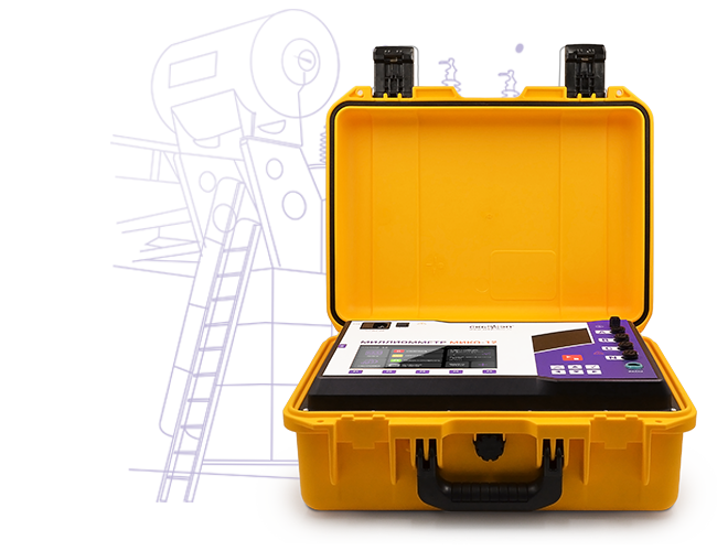
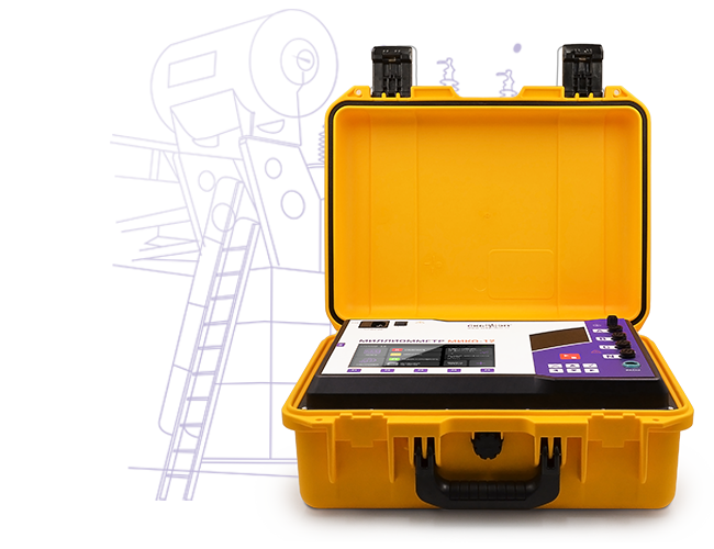
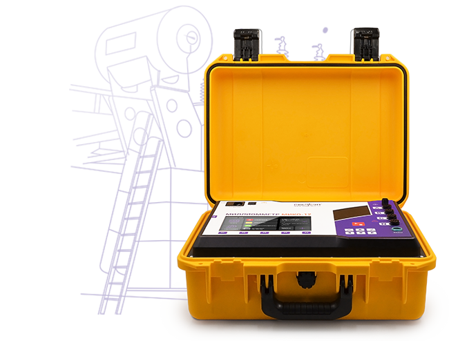
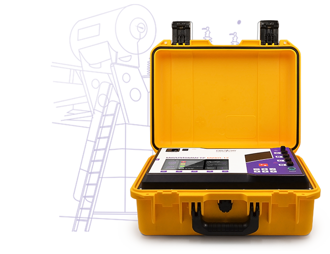
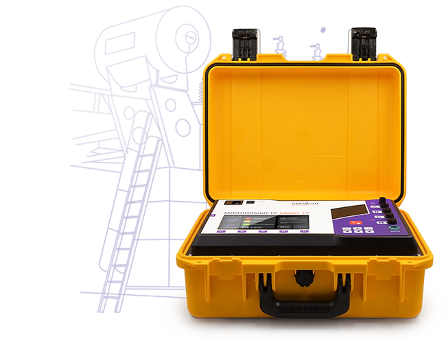
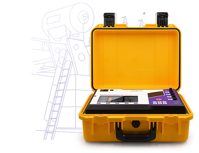
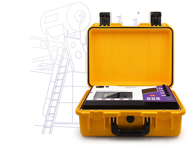
MIKO-12-50A three-phase milli-ohmmeter is designed to measure DC resistance in the range of 1 μΩ to 100 kΩ at a current up to 50 A in inductive and non-inductive power equipment.
MIKO-12-50A diagnostic objects:
Windings of high-power transformers;
Windings of instrument transformers and other high-inductive equipment;
Windings of electric motors, generators, and linear compensators;
Electromagnet windings;
Contacts of circuit breakers, busbars, resistors, and other non-inductive circuits;
Compensating, current-limiting, and other resistors of high-voltage circuit breakers;
Cables.
Test current within a range of up to 50 A can be set in two ways:
Selection from a set of fixed values;
Automatic test current setting.
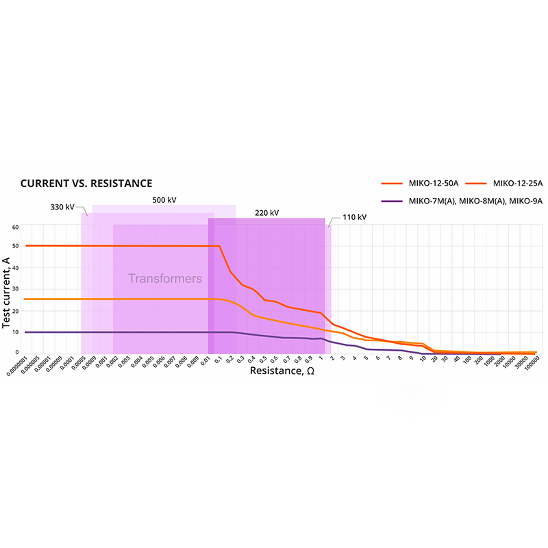
In Auto mode, the device automatically determines the optimal test current and simultaneously calculates the resistance of the diagnostic object, ensuring high measurement accuracy and precision.
MIKO-12-50A
MIKO-12-25A
MIKO-9A
MIKO-8M(A)
MIKO-7M(A)
Resistance range
1 μΩ – 100 kΩ
1 μΩ – 50 kΩ
1 μΩ – 30 kΩ
1 μΩ – 10 kΩ
1 μΩ – 2 kΩ
Test current
0.2 mA – 50 A
0.2 mA – 25 A
0.0005 A – 10 A
0.001 – 10 A
0.01 – 10 A
Output capacity, max
400 W
400 W
60 W
60 W
60 W
Number of measurement channels
5 pcs.
5 pcs.
2 pcs.
1 pc.
1 pc.
Three-phase sequential measurement
Three-phase simultaneous measurement
Automatic control of the OLTC drive
Fast method for extinguishing self-induction EMF
[~DETAIL_TEXT] =>
MIKO-12-50A three-phase milli-ohmmeter is designed to measure DC resistance in the range of 1 μΩ to 100 kΩ at a current up to 50 A in inductive and non-inductive power equipment.
MIKO-12-50A diagnostic objects:
Windings of high-power transformers;
Windings of instrument transformers and other high-inductive equipment;
Windings of electric motors, generators, and linear compensators;
Electromagnet windings;
Contacts of circuit breakers, busbars, resistors, and other non-inductive circuits;
Compensating, current-limiting, and other resistors of high-voltage circuit breakers;
Cables.
Test current within a range of up to 50 A can be set in two ways:
Selection from a set of fixed values;
Automatic test current setting.
In Auto mode, the device automatically determines the optimal test current and simultaneously calculates the resistance of the diagnostic object, ensuring high measurement accuracy and precision.
MIKO-12-50A
MIKO-12-25A
MIKO-9A
MIKO-8M(A)
MIKO-7M(A)
Resistance range
1 μΩ – 100 kΩ
1 μΩ – 50 kΩ
1 μΩ – 30 kΩ
1 μΩ – 10 kΩ
1 μΩ – 2 kΩ
Test current
0.2 mA – 50 A
0.2 mA – 25 A
0.0005 A – 10 A
0.001 – 10 A
0.01 – 10 A
Output capacity, max
400 W
400 W
60 W
60 W
60 W
Number of measurement channels
5 pcs.
5 pcs.
2 pcs.
1 pc.
1 pc.
Three-phase sequential measurement
Three-phase simultaneous measurement
Automatic control of the OLTC drive
Fast method for extinguishing self-induction EMF
[SORT] => 10
[~SORT] => 10
[DETAIL_TEXT_TYPE] => html
[~DETAIL_TEXT_TYPE] => html
[PROPERTIES] => Array
(
[PREVIEW_ICON] => Array
(
[ID] => 310
[TIMESTAMP_X] => 2019-11-18 14:18:31
[IBLOCK_ID] => 102
[NAME] => Иконка для анонса
[ACTIVE] => Y
[SORT] => 500
[CODE] => PREVIEW_ICON
[DEFAULT_VALUE] =>
[PROPERTY_TYPE] => F
[ROW_COUNT] => 1
[COL_COUNT] => 50
[LIST_TYPE] => L
[MULTIPLE] => N
[XML_ID] => 28
[FILE_TYPE] => jpg, png, jpeg
[MULTIPLE_CNT] => 5
[TMP_ID] =>
[LINK_IBLOCK_ID] => 0
[WITH_DESCRIPTION] => N
[SEARCHABLE] => N
[FILTRABLE] => N
[IS_REQUIRED] => Y
[VERSION] => 1
[USER_TYPE] =>
[USER_TYPE_SETTINGS] =>
[HINT] =>
[PROPERTY_VALUE_ID] => 101430
[VALUE] => 42704
[DESCRIPTION] =>
[VALUE_ENUM] =>
[VALUE_XML_ID] =>
[VALUE_SORT] =>
[~VALUE] => 42704
[~DESCRIPTION] =>
[~NAME] => Иконка для анонса
[~DEFAULT_VALUE] =>
)
[DETAIL_ICON] => Array
(
[ID] => 311
[TIMESTAMP_X] => 2019-11-18 14:18:31
[IBLOCK_ID] => 102
[NAME] => Иконка для описания
[ACTIVE] => Y
[SORT] => 500
[CODE] => DETAIL_ICON
[DEFAULT_VALUE] =>
[PROPERTY_TYPE] => F
[ROW_COUNT] => 1
[COL_COUNT] => 50
[LIST_TYPE] => L
[MULTIPLE] => N
[XML_ID] => 29
[FILE_TYPE] => jpg, png, jpeg
[MULTIPLE_CNT] => 5
[TMP_ID] =>
[LINK_IBLOCK_ID] => 0
[WITH_DESCRIPTION] => N
[SEARCHABLE] => N
[FILTRABLE] => N
[IS_REQUIRED] => Y
[VERSION] => 1
[USER_TYPE] =>
[USER_TYPE_SETTINGS] =>
[HINT] =>
[PROPERTY_VALUE_ID] => 101431
[VALUE] => 42705
[DESCRIPTION] =>
[VALUE_ENUM] =>
[VALUE_XML_ID] =>
[VALUE_SORT] =>
[~VALUE] => 42705
[~DESCRIPTION] =>
[~NAME] => Иконка для описания
[~DEFAULT_VALUE] =>
)
[MORE_PHOTO] => Array
(
[ID] => 312
[TIMESTAMP_X] => 2019-11-18 14:18:31
[IBLOCK_ID] => 102
[NAME] => Фотографии
[ACTIVE] => Y
[SORT] => 500
[CODE] => MORE_PHOTO
[DEFAULT_VALUE] =>
[PROPERTY_TYPE] => F
[ROW_COUNT] => 1
[COL_COUNT] => 50
[LIST_TYPE] => L
[MULTIPLE] => Y
[XML_ID] => 30
[FILE_TYPE] => jpg, png, jpeg
[MULTIPLE_CNT] => 5
[TMP_ID] =>
[LINK_IBLOCK_ID] => 0
[WITH_DESCRIPTION] => Y
[SEARCHABLE] => N
[FILTRABLE] => N
[IS_REQUIRED] => N
[VERSION] => 1
[USER_TYPE] =>
[USER_TYPE_SETTINGS] =>
[HINT] =>
[PROPERTY_VALUE_ID] =>
[VALUE] =>
[DESCRIPTION] =>
[VALUE_ENUM] =>
[VALUE_XML_ID] =>
[VALUE_SORT] =>
[~VALUE] =>
[~DESCRIPTION] =>
[~NAME] => Фотографии
[~DEFAULT_VALUE] =>
)
)
)
Array
(
[ID] => 30564
[~ID] => 30564
[NAME] => High and ultra-high power transformers diagnostics
[~NAME] => High and ultra-high power transformers diagnostics
[IBLOCK_ID] => 102
[~IBLOCK_ID] => 102
[DETAIL_TEXT] =>
Such diagnostics present several technical challenges, including high inductance,
unstable measurement signals, and prolonged transient processes at low currents.
These factors increase testing time and may reduce the accuracy of the results.
MIKO-12-50A is designed to operate effectively under these conditions.
The device generates an output current of 50 A at a voltage of 50 V, ensuring a
stable measurement signal and accelerated saturation of the transformer's magnetic
circuit.
Contrary to most similar solutions, the device provides an output power of up to
400 W at the measured resistance. This significantly reduces the impact of transient
processes and improves the accuracy of resistance measurements for the high-voltage (HV)
and low-voltage (LV) windings of high-power transformers.
[~DETAIL_TEXT] =>
Such diagnostics present several technical challenges, including high inductance,
unstable measurement signals, and prolonged transient processes at low currents.
These factors increase testing time and may reduce the accuracy of the results.
MIKO-12-50A is designed to operate effectively under these conditions.
The device generates an output current of 50 A at a voltage of 50 V, ensuring a
stable measurement signal and accelerated saturation of the transformer's magnetic
circuit.
Contrary to most similar solutions, the device provides an output power of up to
400 W at the measured resistance. This significantly reduces the impact of transient
processes and improves the accuracy of resistance measurements for the high-voltage (HV)
and low-voltage (LV) windings of high-power transformers.
[SORT] => 20
[~SORT] => 20
[DETAIL_TEXT_TYPE] => html
[~DETAIL_TEXT_TYPE] => html
[PROPERTIES] => Array
(
[PREVIEW_ICON] => Array
(
[ID] => 310
[TIMESTAMP_X] => 2019-11-18 14:18:31
[IBLOCK_ID] => 102
[NAME] => Иконка для анонса
[ACTIVE] => Y
[SORT] => 500
[CODE] => PREVIEW_ICON
[DEFAULT_VALUE] =>
[PROPERTY_TYPE] => F
[ROW_COUNT] => 1
[COL_COUNT] => 50
[LIST_TYPE] => L
[MULTIPLE] => N
[XML_ID] => 28
[FILE_TYPE] => jpg, png, jpeg
[MULTIPLE_CNT] => 5
[TMP_ID] =>
[LINK_IBLOCK_ID] => 0
[WITH_DESCRIPTION] => N
[SEARCHABLE] => N
[FILTRABLE] => N
[IS_REQUIRED] => Y
[VERSION] => 1
[USER_TYPE] =>
[USER_TYPE_SETTINGS] =>
[HINT] =>
[PROPERTY_VALUE_ID] => 101434
[VALUE] => 42707
[DESCRIPTION] =>
[VALUE_ENUM] =>
[VALUE_XML_ID] =>
[VALUE_SORT] =>
[~VALUE] => 42707
[~DESCRIPTION] =>
[~NAME] => Иконка для анонса
[~DEFAULT_VALUE] =>
)
[DETAIL_ICON] => Array
(
[ID] => 311
[TIMESTAMP_X] => 2019-11-18 14:18:31
[IBLOCK_ID] => 102
[NAME] => Иконка для описания
[ACTIVE] => Y
[SORT] => 500
[CODE] => DETAIL_ICON
[DEFAULT_VALUE] =>
[PROPERTY_TYPE] => F
[ROW_COUNT] => 1
[COL_COUNT] => 50
[LIST_TYPE] => L
[MULTIPLE] => N
[XML_ID] => 29
[FILE_TYPE] => jpg, png, jpeg
[MULTIPLE_CNT] => 5
[TMP_ID] =>
[LINK_IBLOCK_ID] => 0
[WITH_DESCRIPTION] => N
[SEARCHABLE] => N
[FILTRABLE] => N
[IS_REQUIRED] => Y
[VERSION] => 1
[USER_TYPE] =>
[USER_TYPE_SETTINGS] =>
[HINT] =>
[PROPERTY_VALUE_ID] => 101435
[VALUE] => 42708
[DESCRIPTION] =>
[VALUE_ENUM] =>
[VALUE_XML_ID] =>
[VALUE_SORT] =>
[~VALUE] => 42708
[~DESCRIPTION] =>
[~NAME] => Иконка для описания
[~DEFAULT_VALUE] =>
)
[MORE_PHOTO] => Array
(
[ID] => 312
[TIMESTAMP_X] => 2019-11-18 14:18:31
[IBLOCK_ID] => 102
[NAME] => Фотографии
[ACTIVE] => Y
[SORT] => 500
[CODE] => MORE_PHOTO
[DEFAULT_VALUE] =>
[PROPERTY_TYPE] => F
[ROW_COUNT] => 1
[COL_COUNT] => 50
[LIST_TYPE] => L
[MULTIPLE] => Y
[XML_ID] => 30
[FILE_TYPE] => jpg, png, jpeg
[MULTIPLE_CNT] => 5
[TMP_ID] =>
[LINK_IBLOCK_ID] => 0
[WITH_DESCRIPTION] => Y
[SEARCHABLE] => N
[FILTRABLE] => N
[IS_REQUIRED] => N
[VERSION] => 1
[USER_TYPE] =>
[USER_TYPE_SETTINGS] =>
[HINT] =>
[PROPERTY_VALUE_ID] =>
[VALUE] =>
[DESCRIPTION] =>
[VALUE_ENUM] =>
[VALUE_XML_ID] =>
[VALUE_SORT] =>
[~VALUE] =>
[~DESCRIPTION] =>
[~NAME] => Фотографии
[~DEFAULT_VALUE] =>
)
)
)
Array
(
[ID] => 30565
[~ID] => 30565
[NAME] => Special measurement modes for high accuracy
[~NAME] => Special measurement modes for high accuracy
[IBLOCK_ID] => 102
[~IBLOCK_ID] => 102
[DETAIL_TEXT] =>
Depending on the object type, special measurement modes can be selected.
The user can choose one of the following:
Sequential mode – current up to 25 A;
Single mode – current up to 50 A;
Parallel mode – current 12.5 A.
Measurements can be started and stopped manually (by pressing the
START button) or automatically when a predefined criterion is met.
Based on the transformer winding connection diagram, the following measurement modes are available:
2 windings (HV + LV). The test current flows through the
high-voltage and low-voltage windings connected in series while the resistance
of each winding is measured simultaneously. The measurement starts by pressing
the START button and stops automatically or manually.
3 windings – Sequential mode. The device performs automatic
sequential measurements across all three phases with automatic process termination.
The measurement starts by pressing the START button and stops
automatically once the predefined criterion is reached.
3 windings – Parallel mode. Simultaneous automatic measurements
across three phases are a distinctive feature of the MIKO-12-50A. The measurement
starts by pressing the START button and stops automatically when
the predefined criterion is reached or manually. The parallel measurement method
significantly reduces the total testing time, especially when measuring resistance
at all tap positions of the OLTC/NLTC.
[~DETAIL_TEXT] =>
Depending on the object type, special measurement modes can be selected.
The user can choose one of the following:
Sequential mode – current up to 25 A;
Single mode – current up to 50 A;
Parallel mode – current 12.5 A.
Measurements can be started and stopped manually (by pressing the
START button) or automatically when a predefined criterion is met.
Based on the transformer winding connection diagram, the following measurement modes are available:
2 windings (HV + LV). The test current flows through the
high-voltage and low-voltage windings connected in series while the resistance
of each winding is measured simultaneously. The measurement starts by pressing
the START button and stops automatically or manually.
3 windings – Sequential mode. The device performs automatic
sequential measurements across all three phases with automatic process termination.
The measurement starts by pressing the START button and stops
automatically once the predefined criterion is reached.
3 windings – Parallel mode. Simultaneous automatic measurements
across three phases are a distinctive feature of the MIKO-12-50A. The measurement
starts by pressing the START button and stops automatically when
the predefined criterion is reached or manually. The parallel measurement method
significantly reduces the total testing time, especially when measuring resistance
at all tap positions of the OLTC/NLTC.
[SORT] => 30
[~SORT] => 30
[DETAIL_TEXT_TYPE] => html
[~DETAIL_TEXT_TYPE] => html
[PROPERTIES] => Array
(
[PREVIEW_ICON] => Array
(
[ID] => 310
[TIMESTAMP_X] => 2019-11-18 14:18:31
[IBLOCK_ID] => 102
[NAME] => Иконка для анонса
[ACTIVE] => Y
[SORT] => 500
[CODE] => PREVIEW_ICON
[DEFAULT_VALUE] =>
[PROPERTY_TYPE] => F
[ROW_COUNT] => 1
[COL_COUNT] => 50
[LIST_TYPE] => L
[MULTIPLE] => N
[XML_ID] => 28
[FILE_TYPE] => jpg, png, jpeg
[MULTIPLE_CNT] => 5
[TMP_ID] =>
[LINK_IBLOCK_ID] => 0
[WITH_DESCRIPTION] => N
[SEARCHABLE] => N
[FILTRABLE] => N
[IS_REQUIRED] => Y
[VERSION] => 1
[USER_TYPE] =>
[USER_TYPE_SETTINGS] =>
[HINT] =>
[PROPERTY_VALUE_ID] => 101436
[VALUE] => 42710
[DESCRIPTION] =>
[VALUE_ENUM] =>
[VALUE_XML_ID] =>
[VALUE_SORT] =>
[~VALUE] => 42710
[~DESCRIPTION] =>
[~NAME] => Иконка для анонса
[~DEFAULT_VALUE] =>
)
[DETAIL_ICON] => Array
(
[ID] => 311
[TIMESTAMP_X] => 2019-11-18 14:18:31
[IBLOCK_ID] => 102
[NAME] => Иконка для описания
[ACTIVE] => Y
[SORT] => 500
[CODE] => DETAIL_ICON
[DEFAULT_VALUE] =>
[PROPERTY_TYPE] => F
[ROW_COUNT] => 1
[COL_COUNT] => 50
[LIST_TYPE] => L
[MULTIPLE] => N
[XML_ID] => 29
[FILE_TYPE] => jpg, png, jpeg
[MULTIPLE_CNT] => 5
[TMP_ID] =>
[LINK_IBLOCK_ID] => 0
[WITH_DESCRIPTION] => N
[SEARCHABLE] => N
[FILTRABLE] => N
[IS_REQUIRED] => Y
[VERSION] => 1
[USER_TYPE] =>
[USER_TYPE_SETTINGS] =>
[HINT] =>
[PROPERTY_VALUE_ID] => 101437
[VALUE] => 42711
[DESCRIPTION] =>
[VALUE_ENUM] =>
[VALUE_XML_ID] =>
[VALUE_SORT] =>
[~VALUE] => 42711
[~DESCRIPTION] =>
[~NAME] => Иконка для описания
[~DEFAULT_VALUE] =>
)
[MORE_PHOTO] => Array
(
[ID] => 312
[TIMESTAMP_X] => 2019-11-18 14:18:31
[IBLOCK_ID] => 102
[NAME] => Фотографии
[ACTIVE] => Y
[SORT] => 500
[CODE] => MORE_PHOTO
[DEFAULT_VALUE] =>
[PROPERTY_TYPE] => F
[ROW_COUNT] => 1
[COL_COUNT] => 50
[LIST_TYPE] => L
[MULTIPLE] => Y
[XML_ID] => 30
[FILE_TYPE] => jpg, png, jpeg
[MULTIPLE_CNT] => 5
[TMP_ID] =>
[LINK_IBLOCK_ID] => 0
[WITH_DESCRIPTION] => Y
[SEARCHABLE] => N
[FILTRABLE] => N
[IS_REQUIRED] => N
[VERSION] => 1
[USER_TYPE] =>
[USER_TYPE_SETTINGS] =>
[HINT] =>
[PROPERTY_VALUE_ID] => Array
(
[0] => 101438
[1] => 101439
[2] => 101440
)
[VALUE] => Array
(
[0] => 42712
[1] => 42713
[2] => 42714
)
[DESCRIPTION] => Array
(
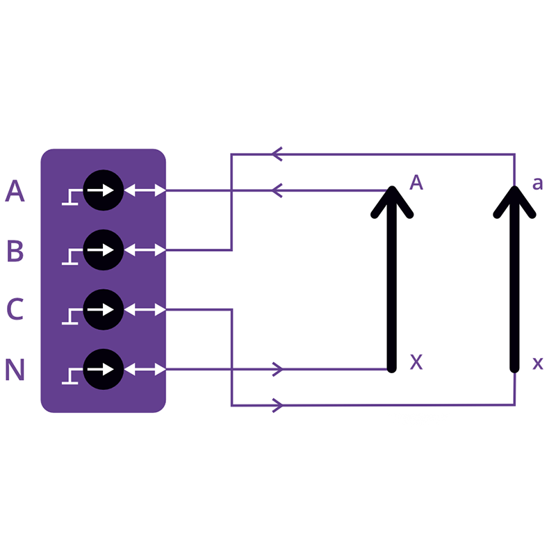
[0] => Connecting the MIKO-12-50A to a three-phase transformer
[1] => Connecting the MIKO-12-50A to a single-phase transformer
[2] => Connecting the MIKO-12-50A to the Y0 (Star with Neutral) transformer
)
[VALUE_ENUM] =>
[VALUE_XML_ID] =>
[VALUE_SORT] =>
[~VALUE] => Array
(
[0] => 42712
[1] => 42713
[2] => 42714
)
[~DESCRIPTION] => Array
(
[0] => Connecting the MIKO-12-50A to a three-phase transformer
[1] => Connecting the MIKO-12-50A to a single-phase transformer
[2] => Connecting the MIKO-12-50A to the Y0 (Star with Neutral) transformer
)
[~NAME] => Фотографии
[~DEFAULT_VALUE] =>
)
)
)
Array
(
[ID] => 30566
[~ID] => 30566
[NAME] => Automatic calculations and comparison of measurement results with nominal values
[~NAME] => Automatic calculations and comparison of measurement results with nominal values
[IBLOCK_ID] => 102
[~IBLOCK_ID] => 102
[DETAIL_TEXT] =>
The device can automatically calculate the parameters specified in technical inspection regulations:
Calculation of the relative difference in winding resistance;
Conversion of measured resistance values to the nominal temperature;
Calculation of phase winding resistance based on the measured line resistances;
Automatic identification of phases with a relative resistance deviation exceeding 2%.
The device automatically compares the measured results with the nominal values.
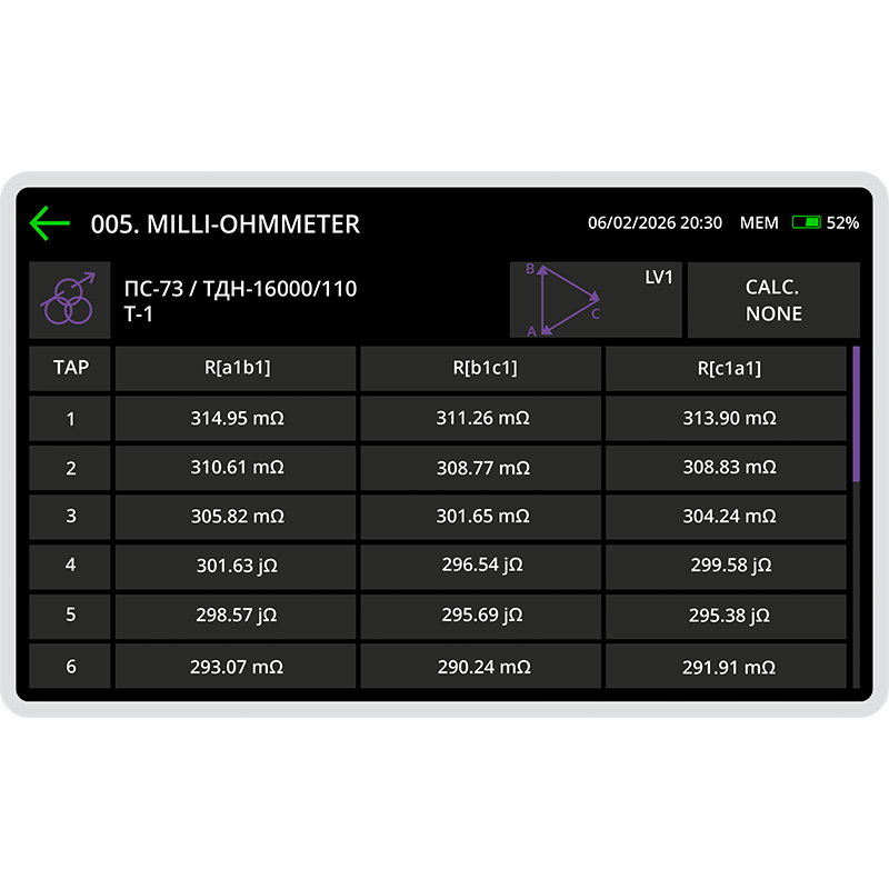
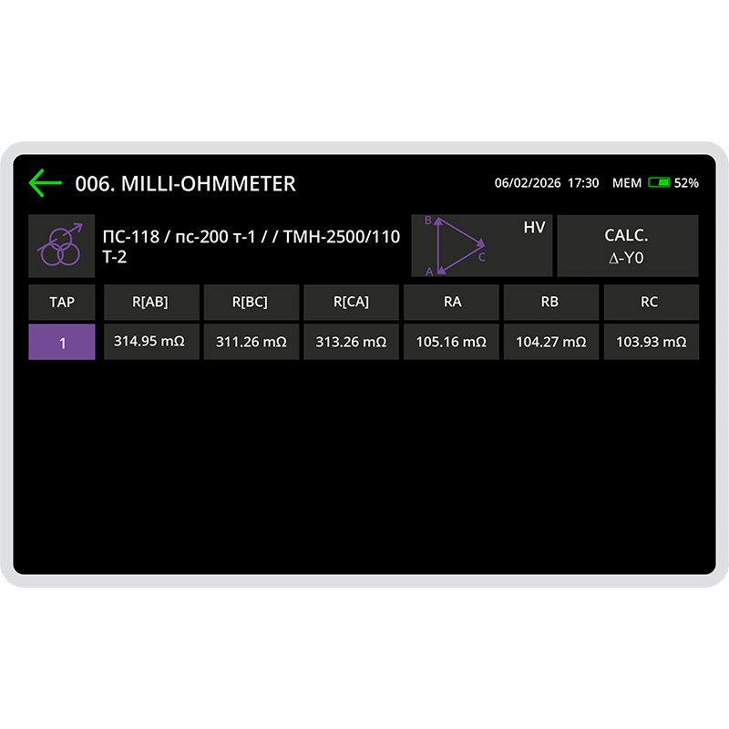
Once the measurement is complete, the calculated results are displayed on the screen,
allowing the user to quickly determine whether the equipment is suitable for further operation.
[~DETAIL_TEXT] =>
The device can automatically calculate the parameters specified in technical inspection regulations:
Calculation of the relative difference in winding resistance;
Conversion of measured resistance values to the nominal temperature;
Calculation of phase winding resistance based on the measured line resistances;
Automatic identification of phases with a relative resistance deviation exceeding 2%.
The device automatically compares the measured results with the nominal values.
Once the measurement is complete, the calculated results are displayed on the screen,
allowing the user to quickly determine whether the equipment is suitable for further operation.
[SORT] => 40
[~SORT] => 40
[DETAIL_TEXT_TYPE] => html
[~DETAIL_TEXT_TYPE] => html
[PROPERTIES] => Array
(
[PREVIEW_ICON] => Array
(
[ID] => 310
[TIMESTAMP_X] => 2019-11-18 14:18:31
[IBLOCK_ID] => 102
[NAME] => Иконка для анонса
[ACTIVE] => Y
[SORT] => 500
[CODE] => PREVIEW_ICON
[DEFAULT_VALUE] =>
[PROPERTY_TYPE] => F
[ROW_COUNT] => 1
[COL_COUNT] => 50
[LIST_TYPE] => L
[MULTIPLE] => N
[XML_ID] => 28
[FILE_TYPE] => jpg, png, jpeg
[MULTIPLE_CNT] => 5
[TMP_ID] =>
[LINK_IBLOCK_ID] => 0
[WITH_DESCRIPTION] => N
[SEARCHABLE] => N
[FILTRABLE] => N
[IS_REQUIRED] => Y
[VERSION] => 1
[USER_TYPE] =>
[USER_TYPE_SETTINGS] =>
[HINT] =>
[PROPERTY_VALUE_ID] => 101441
[VALUE] => 42716
[DESCRIPTION] =>
[VALUE_ENUM] =>
[VALUE_XML_ID] =>
[VALUE_SORT] =>
[~VALUE] => 42716
[~DESCRIPTION] =>
[~NAME] => Иконка для анонса
[~DEFAULT_VALUE] =>
)
[DETAIL_ICON] => Array
(
[ID] => 311
[TIMESTAMP_X] => 2019-11-18 14:18:31
[IBLOCK_ID] => 102
[NAME] => Иконка для описания
[ACTIVE] => Y
[SORT] => 500
[CODE] => DETAIL_ICON
[DEFAULT_VALUE] =>
[PROPERTY_TYPE] => F
[ROW_COUNT] => 1
[COL_COUNT] => 50
[LIST_TYPE] => L
[MULTIPLE] => N
[XML_ID] => 29
[FILE_TYPE] => jpg, png, jpeg
[MULTIPLE_CNT] => 5
[TMP_ID] =>
[LINK_IBLOCK_ID] => 0
[WITH_DESCRIPTION] => N
[SEARCHABLE] => N
[FILTRABLE] => N
[IS_REQUIRED] => Y
[VERSION] => 1
[USER_TYPE] =>
[USER_TYPE_SETTINGS] =>
[HINT] =>
[PROPERTY_VALUE_ID] => 101442
[VALUE] => 42717
[DESCRIPTION] =>
[VALUE_ENUM] =>
[VALUE_XML_ID] =>
[VALUE_SORT] =>
[~VALUE] => 42717
[~DESCRIPTION] =>
[~NAME] => Иконка для описания
[~DEFAULT_VALUE] =>
)
[MORE_PHOTO] => Array
(
[ID] => 312
[TIMESTAMP_X] => 2019-11-18 14:18:31
[IBLOCK_ID] => 102
[NAME] => Фотографии
[ACTIVE] => Y
[SORT] => 500
[CODE] => MORE_PHOTO
[DEFAULT_VALUE] =>
[PROPERTY_TYPE] => F
[ROW_COUNT] => 1
[COL_COUNT] => 50
[LIST_TYPE] => L
[MULTIPLE] => Y
[XML_ID] => 30
[FILE_TYPE] => jpg, png, jpeg
[MULTIPLE_CNT] => 5
[TMP_ID] =>
[LINK_IBLOCK_ID] => 0
[WITH_DESCRIPTION] => Y
[SEARCHABLE] => N
[FILTRABLE] => N
[IS_REQUIRED] => N
[VERSION] => 1
[USER_TYPE] =>
[USER_TYPE_SETTINGS] =>
[HINT] =>
[PROPERTY_VALUE_ID] =>
[VALUE] =>
[DESCRIPTION] =>
[VALUE_ENUM] =>
[VALUE_XML_ID] =>
[VALUE_SORT] =>
[~VALUE] =>
[~DESCRIPTION] =>
[~NAME] => Фотографии
[~DEFAULT_VALUE] =>
)
)
)
Array
(
[ID] => 30567
[~ID] => 30567
[NAME] => Automatic control of the OLTC drive
[~NAME] => Automatic control of the OLTC drive
[IBLOCK_ID] => 102
[~IBLOCK_ID] => 102
[DETAIL_TEXT] =>
The device is equipped with an automatic OLTC position switching function for use during the measurement process. Once a stable resistance is reached, a signal is sent to the OLTC drive to switch to the next tap position, allowing the measurement process to continue.
This feature eliminates the need for specialists to constantly monitor the instrument's readings and manually switch the OLTC. It significantly simplifies the measurement procedure and reduces the time required for diagnostics.
[~DETAIL_TEXT] =>
The device is equipped with an automatic OLTC position switching function for use during the measurement process. Once a stable resistance is reached, a signal is sent to the OLTC drive to switch to the next tap position, allowing the measurement process to continue.
This feature eliminates the need for specialists to constantly monitor the instrument's readings and manually switch the OLTC. It significantly simplifies the measurement procedure and reduces the time required for diagnostics.
[SORT] => 50
[~SORT] => 50
[DETAIL_TEXT_TYPE] => html
[~DETAIL_TEXT_TYPE] => html
[PROPERTIES] => Array
(
[PREVIEW_ICON] => Array
(
[ID] => 310
[TIMESTAMP_X] => 2019-11-18 14:18:31
[IBLOCK_ID] => 102
[NAME] => Иконка для анонса
[ACTIVE] => Y
[SORT] => 500
[CODE] => PREVIEW_ICON
[DEFAULT_VALUE] =>
[PROPERTY_TYPE] => F
[ROW_COUNT] => 1
[COL_COUNT] => 50
[LIST_TYPE] => L
[MULTIPLE] => N
[XML_ID] => 28
[FILE_TYPE] => jpg, png, jpeg
[MULTIPLE_CNT] => 5
[TMP_ID] =>
[LINK_IBLOCK_ID] => 0
[WITH_DESCRIPTION] => N
[SEARCHABLE] => N
[FILTRABLE] => N
[IS_REQUIRED] => Y
[VERSION] => 1
[USER_TYPE] =>
[USER_TYPE_SETTINGS] =>
[HINT] =>
[PROPERTY_VALUE_ID] => 101443
[VALUE] => 42719
[DESCRIPTION] =>
[VALUE_ENUM] =>
[VALUE_XML_ID] =>
[VALUE_SORT] =>
[~VALUE] => 42719
[~DESCRIPTION] =>
[~NAME] => Иконка для анонса
[~DEFAULT_VALUE] =>
)
[DETAIL_ICON] => Array
(
[ID] => 311
[TIMESTAMP_X] => 2019-11-18 14:18:31
[IBLOCK_ID] => 102
[NAME] => Иконка для описания
[ACTIVE] => Y
[SORT] => 500
[CODE] => DETAIL_ICON
[DEFAULT_VALUE] =>
[PROPERTY_TYPE] => F
[ROW_COUNT] => 1
[COL_COUNT] => 50
[LIST_TYPE] => L
[MULTIPLE] => N
[XML_ID] => 29
[FILE_TYPE] => jpg, png, jpeg
[MULTIPLE_CNT] => 5
[TMP_ID] =>
[LINK_IBLOCK_ID] => 0
[WITH_DESCRIPTION] => N
[SEARCHABLE] => N
[FILTRABLE] => N
[IS_REQUIRED] => Y
[VERSION] => 1
[USER_TYPE] =>
[USER_TYPE_SETTINGS] =>
[HINT] =>
[PROPERTY_VALUE_ID] => 101444
[VALUE] => 42720
[DESCRIPTION] =>
[VALUE_ENUM] =>
[VALUE_XML_ID] =>
[VALUE_SORT] =>
[~VALUE] => 42720
[~DESCRIPTION] =>
[~NAME] => Иконка для описания
[~DEFAULT_VALUE] =>
)
[MORE_PHOTO] => Array
(
[ID] => 312
[TIMESTAMP_X] => 2019-11-18 14:18:31
[IBLOCK_ID] => 102
[NAME] => Фотографии
[ACTIVE] => Y
[SORT] => 500
[CODE] => MORE_PHOTO
[DEFAULT_VALUE] =>
[PROPERTY_TYPE] => F
[ROW_COUNT] => 1
[COL_COUNT] => 50
[LIST_TYPE] => L
[MULTIPLE] => Y
[XML_ID] => 30
[FILE_TYPE] => jpg, png, jpeg
[MULTIPLE_CNT] => 5
[TMP_ID] =>
[LINK_IBLOCK_ID] => 0
[WITH_DESCRIPTION] => Y
[SEARCHABLE] => N
[FILTRABLE] => N
[IS_REQUIRED] => N
[VERSION] => 1
[USER_TYPE] =>
[USER_TYPE_SETTINGS] =>
[HINT] =>
[PROPERTY_VALUE_ID] =>
[VALUE] =>
[DESCRIPTION] =>
[VALUE_ENUM] =>
[VALUE_XML_ID] =>
[VALUE_SORT] =>
[~VALUE] =>
[~DESCRIPTION] =>
[~NAME] => Фотографии
[~DEFAULT_VALUE] =>
)
)
)
MIKO-12-50A is equipped with a demagnetization mode, which is required for certain diagnostic tests and for eliminating the remanent magnetism of the transformer magnetic core.
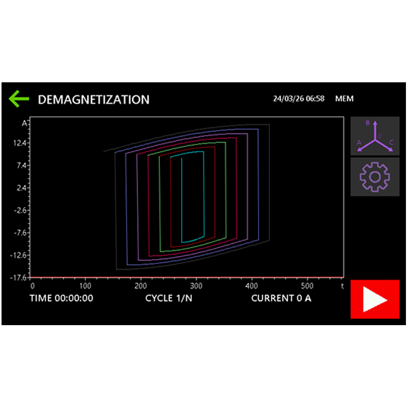
Demagnetization is performed automatically. The device sequentially applies electric current to the selected winding in both forward and reverse directions. With each polarity reversal, the current gradually decreases, ensuring effective removal of the remanent magnetism from the transformer magnetic core. The demagnetization process stops automatically when the current reaches the threshold value or upon the user's command.
The current variation is displayed on the device screen as a real-time graph, allowing the user to monitor and control the demagnetization process.
[~DETAIL_TEXT] =>
MIKO-12-50A is equipped with a demagnetization mode, which is required for certain diagnostic tests and for eliminating the remanent magnetism of the transformer magnetic core.
Demagnetization is performed automatically. The device sequentially applies electric current to the selected winding in both forward and reverse directions. With each polarity reversal, the current gradually decreases, ensuring effective removal of the remanent magnetism from the transformer magnetic core. The demagnetization process stops automatically when the current reaches the threshold value or upon the user's command.
The current variation is displayed on the device screen as a real-time graph, allowing the user to monitor and control the demagnetization process.
[SORT] => 60
[~SORT] => 60
[DETAIL_TEXT_TYPE] => html
[~DETAIL_TEXT_TYPE] => html
[PROPERTIES] => Array
(
[PREVIEW_ICON] => Array
(
[ID] => 310
[TIMESTAMP_X] => 2019-11-18 14:18:31
[IBLOCK_ID] => 102
[NAME] => Иконка для анонса
[ACTIVE] => Y
[SORT] => 500
[CODE] => PREVIEW_ICON
[DEFAULT_VALUE] =>
[PROPERTY_TYPE] => F
[ROW_COUNT] => 1
[COL_COUNT] => 50
[LIST_TYPE] => L
[MULTIPLE] => N
[XML_ID] => 28
[FILE_TYPE] => jpg, png, jpeg
[MULTIPLE_CNT] => 5
[TMP_ID] =>
[LINK_IBLOCK_ID] => 0
[WITH_DESCRIPTION] => N
[SEARCHABLE] => N
[FILTRABLE] => N
[IS_REQUIRED] => Y
[VERSION] => 1
[USER_TYPE] =>
[USER_TYPE_SETTINGS] =>
[HINT] =>
[PROPERTY_VALUE_ID] => 101445
[VALUE] => 42722
[DESCRIPTION] =>
[VALUE_ENUM] =>
[VALUE_XML_ID] =>
[VALUE_SORT] =>
[~VALUE] => 42722
[~DESCRIPTION] =>
[~NAME] => Иконка для анонса
[~DEFAULT_VALUE] =>
)
[DETAIL_ICON] => Array
(
[ID] => 311
[TIMESTAMP_X] => 2019-11-18 14:18:31
[IBLOCK_ID] => 102
[NAME] => Иконка для описания
[ACTIVE] => Y
[SORT] => 500
[CODE] => DETAIL_ICON
[DEFAULT_VALUE] =>
[PROPERTY_TYPE] => F
[ROW_COUNT] => 1
[COL_COUNT] => 50
[LIST_TYPE] => L
[MULTIPLE] => N
[XML_ID] => 29
[FILE_TYPE] => jpg, png, jpeg
[MULTIPLE_CNT] => 5
[TMP_ID] =>
[LINK_IBLOCK_ID] => 0
[WITH_DESCRIPTION] => N
[SEARCHABLE] => N
[FILTRABLE] => N
[IS_REQUIRED] => Y
[VERSION] => 1
[USER_TYPE] =>
[USER_TYPE_SETTINGS] =>
[HINT] =>
[PROPERTY_VALUE_ID] => 101446
[VALUE] => 42723
[DESCRIPTION] =>
[VALUE_ENUM] =>
[VALUE_XML_ID] =>
[VALUE_SORT] =>
[~VALUE] => 42723
[~DESCRIPTION] =>
[~NAME] => Иконка для описания
[~DEFAULT_VALUE] =>
)
[MORE_PHOTO] => Array
(
[ID] => 312
[TIMESTAMP_X] => 2019-11-18 14:18:31
[IBLOCK_ID] => 102
[NAME] => Фотографии
[ACTIVE] => Y
[SORT] => 500
[CODE] => MORE_PHOTO
[DEFAULT_VALUE] =>
[PROPERTY_TYPE] => F
[ROW_COUNT] => 1
[COL_COUNT] => 50
[LIST_TYPE] => L
[MULTIPLE] => Y
[XML_ID] => 30
[FILE_TYPE] => jpg, png, jpeg
[MULTIPLE_CNT] => 5
[TMP_ID] =>
[LINK_IBLOCK_ID] => 0
[WITH_DESCRIPTION] => Y
[SEARCHABLE] => N
[FILTRABLE] => N
[IS_REQUIRED] => N
[VERSION] => 1
[USER_TYPE] =>
[USER_TYPE_SETTINGS] =>
[HINT] =>
[PROPERTY_VALUE_ID] =>
[VALUE] =>
[DESCRIPTION] =>
[VALUE_ENUM] =>
[VALUE_XML_ID] =>
[VALUE_SORT] =>
[~VALUE] =>
[~DESCRIPTION] =>
[~NAME] => Фотографии
[~DEFAULT_VALUE] =>
)
)
)
Array
(
[ID] => 30569
[~ID] => 30569
[NAME] => Non-intrusive testing of the OLTC (DRM method)
[~NAME] => Non-intrusive testing of the OLTC (DRM method)
[IBLOCK_ID] => 102
[~IBLOCK_ID] => 102
[DETAIL_TEXT] =>
Non-intrusive OLTC testing allows the user to assess the condition of on-load tap changers (OLTCs) with current-limiting resistors without removing the contactor tank cover. This method is known as DRM (Dynamic Resistance Measurement).
The method is based on measuring instantaneous test current values during the tap-changing process. The test current first passes through the transformer winding and then through the OLTC contacts while switching from one tap position to another. Based on these measurements, the device generates a DRM graph that illustrates the current variation throughout the switching process. This graph allows the user to evaluate the tap-changing time and the overall condition of the OLTC.
Analysis of the recorded graphs makes it possible not only to distinguish between fault-free and faulty OLTCs but also to identify the nature of a defect, eliminating the need to open fault-free tap changers.
The milli-ohmmeter mode and the DRM test complement each other, providing comprehensive information about the condition of the transformer.
[~DETAIL_TEXT] =>
Non-intrusive OLTC testing allows the user to assess the condition of on-load tap changers (OLTCs) with current-limiting resistors without removing the contactor tank cover. This method is known as DRM (Dynamic Resistance Measurement).
The method is based on measuring instantaneous test current values during the tap-changing process. The test current first passes through the transformer winding and then through the OLTC contacts while switching from one tap position to another. Based on these measurements, the device generates a DRM graph that illustrates the current variation throughout the switching process. This graph allows the user to evaluate the tap-changing time and the overall condition of the OLTC.
Analysis of the recorded graphs makes it possible not only to distinguish between fault-free and faulty OLTCs but also to identify the nature of a defect, eliminating the need to open fault-free tap changers.
The milli-ohmmeter mode and the DRM test complement each other, providing comprehensive information about the condition of the transformer.
[SORT] => 70
[~SORT] => 70
[DETAIL_TEXT_TYPE] => html
[~DETAIL_TEXT_TYPE] => html
[PROPERTIES] => Array
(
[PREVIEW_ICON] => Array
(
[ID] => 310
[TIMESTAMP_X] => 2019-11-18 14:18:31
[IBLOCK_ID] => 102
[NAME] => Иконка для анонса
[ACTIVE] => Y
[SORT] => 500
[CODE] => PREVIEW_ICON
[DEFAULT_VALUE] =>
[PROPERTY_TYPE] => F
[ROW_COUNT] => 1
[COL_COUNT] => 50
[LIST_TYPE] => L
[MULTIPLE] => N
[XML_ID] => 28
[FILE_TYPE] => jpg, png, jpeg
[MULTIPLE_CNT] => 5
[TMP_ID] =>
[LINK_IBLOCK_ID] => 0
[WITH_DESCRIPTION] => N
[SEARCHABLE] => N
[FILTRABLE] => N
[IS_REQUIRED] => Y
[VERSION] => 1
[USER_TYPE] =>
[USER_TYPE_SETTINGS] =>
[HINT] =>
[PROPERTY_VALUE_ID] => 101447
[VALUE] => 42725
[DESCRIPTION] =>
[VALUE_ENUM] =>
[VALUE_XML_ID] =>
[VALUE_SORT] =>
[~VALUE] => 42725
[~DESCRIPTION] =>
[~NAME] => Иконка для анонса
[~DEFAULT_VALUE] =>
)
[DETAIL_ICON] => Array
(
[ID] => 311
[TIMESTAMP_X] => 2019-11-18 14:18:31
[IBLOCK_ID] => 102
[NAME] => Иконка для описания
[ACTIVE] => Y
[SORT] => 500
[CODE] => DETAIL_ICON
[DEFAULT_VALUE] =>
[PROPERTY_TYPE] => F
[ROW_COUNT] => 1
[COL_COUNT] => 50
[LIST_TYPE] => L
[MULTIPLE] => N
[XML_ID] => 29
[FILE_TYPE] => jpg, png, jpeg
[MULTIPLE_CNT] => 5
[TMP_ID] =>
[LINK_IBLOCK_ID] => 0
[WITH_DESCRIPTION] => N
[SEARCHABLE] => N
[FILTRABLE] => N
[IS_REQUIRED] => Y
[VERSION] => 1
[USER_TYPE] =>
[USER_TYPE_SETTINGS] =>
[HINT] =>
[PROPERTY_VALUE_ID] => 101448
[VALUE] => 42726
[DESCRIPTION] =>
[VALUE_ENUM] =>
[VALUE_XML_ID] =>
[VALUE_SORT] =>
[~VALUE] => 42726
[~DESCRIPTION] =>
[~NAME] => Иконка для описания
[~DEFAULT_VALUE] =>
)
[MORE_PHOTO] => Array
(
[ID] => 312
[TIMESTAMP_X] => 2019-11-18 14:18:31
[IBLOCK_ID] => 102
[NAME] => Фотографии
[ACTIVE] => Y
[SORT] => 500
[CODE] => MORE_PHOTO
[DEFAULT_VALUE] =>
[PROPERTY_TYPE] => F
[ROW_COUNT] => 1
[COL_COUNT] => 50
[LIST_TYPE] => L
[MULTIPLE] => Y
[XML_ID] => 30
[FILE_TYPE] => jpg, png, jpeg
[MULTIPLE_CNT] => 5
[TMP_ID] =>
[LINK_IBLOCK_ID] => 0
[WITH_DESCRIPTION] => Y
[SEARCHABLE] => N
[FILTRABLE] => N
[IS_REQUIRED] => N
[VERSION] => 1
[USER_TYPE] =>
[USER_TYPE_SETTINGS] =>
[HINT] =>
[PROPERTY_VALUE_ID] =>
[VALUE] =>
[DESCRIPTION] =>
[VALUE_ENUM] =>
[VALUE_XML_ID] =>
[VALUE_SORT] =>
[~VALUE] =>
[~DESCRIPTION] =>
[~NAME] => Фотографии
[~DEFAULT_VALUE] =>
)
)
)
Array
(
[ID] => 30570
[~ID] => 30570
[NAME] => Touchscreen display, data transfer and control
[~NAME] => Touchscreen display, data transfer and control
[IBLOCK_ID] => 102
[~IBLOCK_ID] => 102
[DETAIL_TEXT] =>
MIKO-12-50A features a built-in memory capable of storing up to 1,000 measurement records, allowing users to view, copy, or delete saved data. Its lightweight design (10 kg) and compact dimensions make the device easy to transport and convenient for on-site operation.
The device is equipped with a high-brightness color touchscreen display and an intuitive user interface, ensuring convenient operation and easy navigation.
Measurement data can be transferred directly to a PC via Bluetooth or USB.
[~DETAIL_TEXT] =>
MIKO-12-50A features a built-in memory capable of storing up to 1,000 measurement records, allowing users to view, copy, or delete saved data. Its lightweight design (10 kg) and compact dimensions make the device easy to transport and convenient for on-site operation.
The device is equipped with a high-brightness color touchscreen display and an intuitive user interface, ensuring convenient operation and easy navigation.
Measurement data can be transferred directly to a PC via Bluetooth or USB.
[SORT] => 80
[~SORT] => 80
[DETAIL_TEXT_TYPE] => html
[~DETAIL_TEXT_TYPE] => html
[PROPERTIES] => Array
(
[PREVIEW_ICON] => Array
(
[ID] => 310
[TIMESTAMP_X] => 2019-11-18 14:18:31
[IBLOCK_ID] => 102
[NAME] => Иконка для анонса
[ACTIVE] => Y
[SORT] => 500
[CODE] => PREVIEW_ICON
[DEFAULT_VALUE] =>
[PROPERTY_TYPE] => F
[ROW_COUNT] => 1
[COL_COUNT] => 50
[LIST_TYPE] => L
[MULTIPLE] => N
[XML_ID] => 28
[FILE_TYPE] => jpg, png, jpeg
[MULTIPLE_CNT] => 5
[TMP_ID] =>
[LINK_IBLOCK_ID] => 0
[WITH_DESCRIPTION] => N
[SEARCHABLE] => N
[FILTRABLE] => N
[IS_REQUIRED] => Y
[VERSION] => 1
[USER_TYPE] =>
[USER_TYPE_SETTINGS] =>
[HINT] =>
[PROPERTY_VALUE_ID] => 101449
[VALUE] => 42728
[DESCRIPTION] =>
[VALUE_ENUM] =>
[VALUE_XML_ID] =>
[VALUE_SORT] =>
[~VALUE] => 42728
[~DESCRIPTION] =>
[~NAME] => Иконка для анонса
[~DEFAULT_VALUE] =>
)
[DETAIL_ICON] => Array
(
[ID] => 311
[TIMESTAMP_X] => 2019-11-18 14:18:31
[IBLOCK_ID] => 102
[NAME] => Иконка для описания
[ACTIVE] => Y
[SORT] => 500
[CODE] => DETAIL_ICON
[DEFAULT_VALUE] =>
[PROPERTY_TYPE] => F
[ROW_COUNT] => 1
[COL_COUNT] => 50
[LIST_TYPE] => L
[MULTIPLE] => N
[XML_ID] => 29
[FILE_TYPE] => jpg, png, jpeg
[MULTIPLE_CNT] => 5
[TMP_ID] =>
[LINK_IBLOCK_ID] => 0
[WITH_DESCRIPTION] => N
[SEARCHABLE] => N
[FILTRABLE] => N
[IS_REQUIRED] => Y
[VERSION] => 1
[USER_TYPE] =>
[USER_TYPE_SETTINGS] =>
[HINT] =>
[PROPERTY_VALUE_ID] => 101450
[VALUE] => 42729
[DESCRIPTION] =>
[VALUE_ENUM] =>
[VALUE_XML_ID] =>
[VALUE_SORT] =>
[~VALUE] => 42729
[~DESCRIPTION] =>
[~NAME] => Иконка для описания
[~DEFAULT_VALUE] =>
)
[MORE_PHOTO] => Array
(
[ID] => 312
[TIMESTAMP_X] => 2019-11-18 14:18:31
[IBLOCK_ID] => 102
[NAME] => Фотографии
[ACTIVE] => Y
[SORT] => 500
[CODE] => MORE_PHOTO
[DEFAULT_VALUE] =>
[PROPERTY_TYPE] => F
[ROW_COUNT] => 1
[COL_COUNT] => 50
[LIST_TYPE] => L
[MULTIPLE] => Y
[XML_ID] => 30
[FILE_TYPE] => jpg, png, jpeg
[MULTIPLE_CNT] => 5
[TMP_ID] =>
[LINK_IBLOCK_ID] => 0
[WITH_DESCRIPTION] => Y
[SEARCHABLE] => N
[FILTRABLE] => N
[IS_REQUIRED] => N
[VERSION] => 1
[USER_TYPE] =>
[USER_TYPE_SETTINGS] =>
[HINT] =>
[PROPERTY_VALUE_ID] =>
[VALUE] =>
[DESCRIPTION] =>
[VALUE_ENUM] =>
[VALUE_XML_ID] =>
[VALUE_SORT] =>
[~VALUE] =>
[~DESCRIPTION] =>
[~NAME] => Фотографии
[~DEFAULT_VALUE] =>
)
)
)
MIKO-12-50A three-phase milli-ohmmeter is designed to measure DC resistance in the range of 1 μΩ to 100 kΩ at a current up to 50 A in inductive and non-inductive power equipment.
MIKO-12-50A diagnostic objects:
Windings of high-power transformers;
Windings of instrument transformers and other high-inductive equipment;
Windings of electric motors, generators, and linear compensators;
Electromagnet windings;
Contacts of circuit breakers, busbars, resistors, and other non-inductive circuits;
Compensating, current-limiting, and other resistors of high-voltage circuit breakers;
Cables.
Test current within a range of up to 50 A can be set in two ways:
Selection from a set of fixed values;
Automatic test current setting.
In Auto mode, the device automatically determines the optimal test current and simultaneously calculates the resistance of the diagnostic object, ensuring high measurement accuracy and precision.
MIKO-12-50A
MIKO-12-25A
MIKO-9A
MIKO-8M(A)
MIKO-7M(A)
Resistance range
1 μΩ – 100 kΩ
1 μΩ – 50 kΩ
1 μΩ – 30 kΩ
1 μΩ – 10 kΩ
1 μΩ – 2 kΩ
Test current
0.2 mA – 50 A
0.2 mA – 25 A
0.0005 A – 10 A
0.001 – 10 A
0.01 – 10 A
Output capacity, max
400 W
400 W
60 W
60 W
60 W
Number of measurement channels
5 pcs.
5 pcs.
2 pcs.
1 pc.
1 pc.
Three-phase sequential measurement
Three-phase simultaneous measurement
Automatic control of the OLTC drive
Fast method for extinguishing self-induction EMF
Such diagnostics present several technical challenges, including high inductance,
unstable measurement signals, and prolonged transient processes at low currents.
These factors increase testing time and may reduce the accuracy of the results.
MIKO-12-50A is designed to operate effectively under these conditions.
The device generates an output current of 50 A at a voltage of 50 V, ensuring a
stable measurement signal and accelerated saturation of the transformer's magnetic
circuit.
Contrary to most similar solutions, the device provides an output power of up to
400 W at the measured resistance. This significantly reduces the impact of transient
processes and improves the accuracy of resistance measurements for the high-voltage (HV)
and low-voltage (LV) windings of high-power transformers.
Depending on the object type, special measurement modes can be selected.
The user can choose one of the following:
Sequential mode – current up to 25 A;
Single mode – current up to 50 A;
Parallel mode – current 12.5 A.
Measurements can be started and stopped manually (by pressing the
START button) or automatically when a predefined criterion is met.
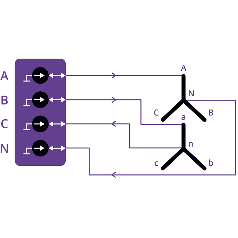
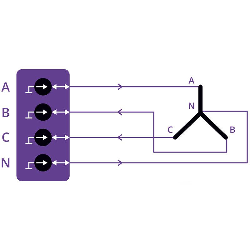
Based on the transformer winding connection diagram, the following measurement modes are available:
2 windings (HV + LV). The test current flows through the
high-voltage and low-voltage windings connected in series while the resistance
of each winding is measured simultaneously. The measurement starts by pressing
the START button and stops automatically or manually.
3 windings – Sequential mode. The device performs automatic
sequential measurements across all three phases with automatic process termination.
The measurement starts by pressing the START button and stops
automatically once the predefined criterion is reached.
3 windings – Parallel mode. Simultaneous automatic measurements
across three phases are a distinctive feature of the MIKO-12-50A. The measurement
starts by pressing the START button and stops automatically when
the predefined criterion is reached or manually. The parallel measurement method
significantly reduces the total testing time, especially when measuring resistance
at all tap positions of the OLTC/NLTC.
The device can automatically calculate the parameters specified in technical inspection regulations:
Calculation of the relative difference in winding resistance;
Conversion of measured resistance values to the nominal temperature;
Calculation of phase winding resistance based on the measured line resistances;
Automatic identification of phases with a relative resistance deviation exceeding 2%.
The device automatically compares the measured results with the nominal values.
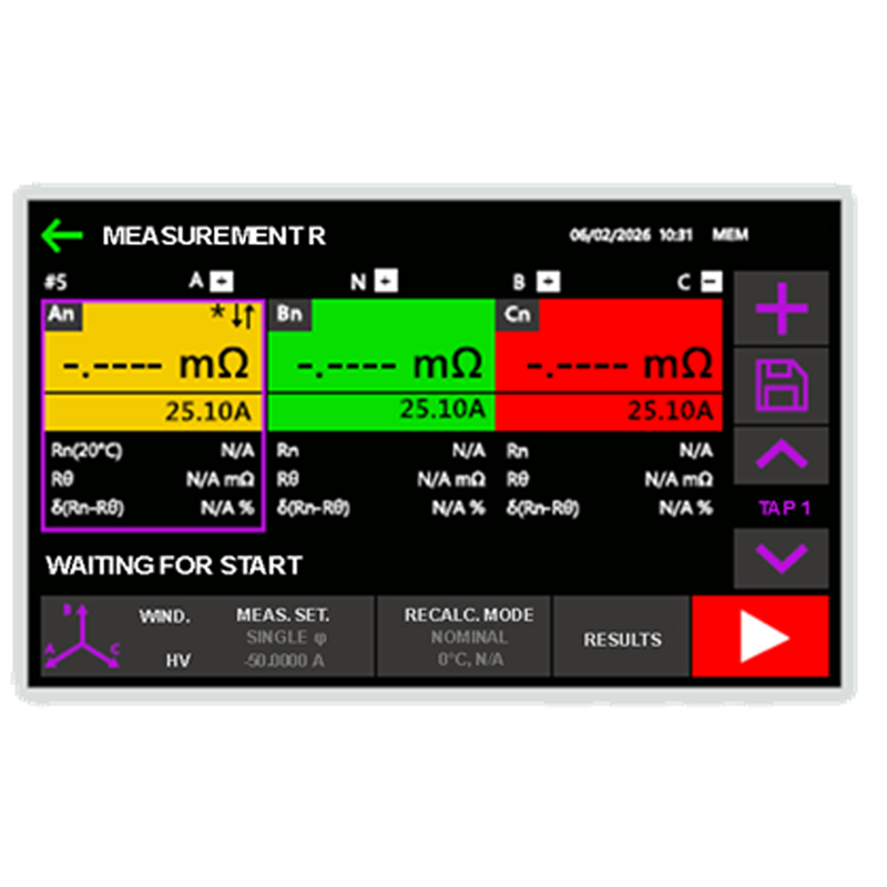
Once the measurement is complete, the calculated results are displayed on the screen,
allowing the user to quickly determine whether the equipment is suitable for further operation.
The device is equipped with an automatic OLTC position switching function for use during the measurement process. Once a stable resistance is reached, a signal is sent to the OLTC drive to switch to the next tap position, allowing the measurement process to continue.
This feature eliminates the need for specialists to constantly monitor the instrument's readings and manually switch the OLTC. It significantly simplifies the measurement procedure and reduces the time required for diagnostics.
MIKO-12-50A is equipped with a demagnetization mode, which is required for certain diagnostic tests and for eliminating the remanent magnetism of the transformer magnetic core.
Demagnetization is performed automatically. The device sequentially applies electric current to the selected winding in both forward and reverse directions. With each polarity reversal, the current gradually decreases, ensuring effective removal of the remanent magnetism from the transformer magnetic core. The demagnetization process stops automatically when the current reaches the threshold value or upon the user's command.
The current variation is displayed on the device screen as a real-time graph, allowing the user to monitor and control the demagnetization process.
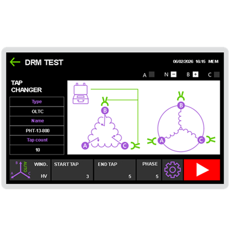
Non-intrusive OLTC testing allows the user to assess the condition of on-load tap changers (OLTCs) with current-limiting resistors without removing the contactor tank cover. This method is known as DRM (Dynamic Resistance Measurement).
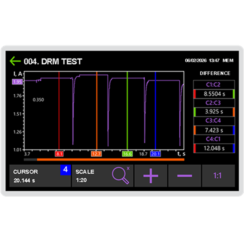
The method is based on measuring instantaneous test current values during the tap-changing process. The test current first passes through the transformer winding and then through the OLTC contacts while switching from one tap position to another. Based on these measurements, the device generates a DRM graph that illustrates the current variation throughout the switching process. This graph allows the user to evaluate the tap-changing time and the overall condition of the OLTC.
Analysis of the recorded graphs makes it possible not only to distinguish between fault-free and faulty OLTCs but also to identify the nature of a defect, eliminating the need to open fault-free tap changers.
The milli-ohmmeter mode and the DRM test complement each other, providing comprehensive information about the condition of the transformer.
MIKO-12-50A features a built-in memory capable of storing up to 1,000 measurement records, allowing users to view, copy, or delete saved data. Its lightweight design (10 kg) and compact dimensions make the device easy to transport and convenient for on-site operation.
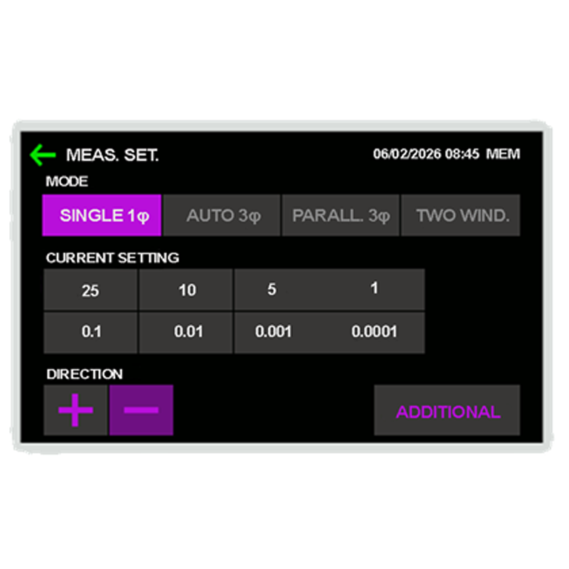
The device is equipped with a high-brightness color touchscreen display and an intuitive user interface, ensuring convenient operation and easy navigation.
Measurement data can be transferred directly to a PC via Bluetooth or USB.
Standard complete set
Photo
Item, Index
Application
Main instrument MIKO-12-50A
Instrument and additional documents: Calibration Certificate, User Manual, Log Book.
Test cable for power transformers
052.20.00.000К
Test cable for power transformers
052.20.00.000К
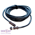
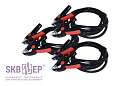
A set of cables 4 x 8.5 m with jaw up to 75 mm for connecting MIKO-12-50A measurement channels to the power transformer bushings of any rating.
Mains cable
018.09.00.000
Mains cable
018.09.00.000
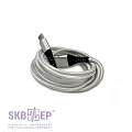
Mains cable 1 x 2 m. For instrument connection to the to the mains.
Ground cable
010.01.00.000
Ground cable
010.01.00.000
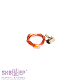
Ground cable 1 x 2 m (0.07 kg) for instrument grounding. The cable is equipped with a C-clamp and a screw end cap. Rated current is 50 А.
Fuse VP2B-1V-2А
Fuse VP2B-1V-2А
For the power source protection.
USB Type-A, USB Type-C Cables 1.5 m 2A
USB cable 1.5 m for charging and connecting devices.
Tool bag
126.06.00.000
Tool bag
126.06.00.000
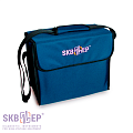
Convenient, robust, wear proof bag for transportation of cables, documentation and other accessories.
Additional complete set (on order)
Photo
Item, Index
Application
Test cable
052.22.00.000
Test cable
052.22.00.000
Test cable 2 x 4 m with jaw up to 20 mm for connecting MIKO-12-50A measurement channels to the current and voltage transformers terminals of any rating.
Test cable extension
031.20.00.000
Test cable extension
031.20.00.000
Recommended to be used together with test cables 052.22.00.000 and 052.20.00.000K.
Made of elastic silicone tube that is resistant to low and high temperatures and corrosive environments. Length: 6.5 m. Weight: 1.18 kg
OLTC drive control cable
052.25.00.000
OLTC drive control cable
052.25.00.000
For sending a signal from the MIKO-12-50A to move the OLTC to a new position, as well as to initiate measurements by the MIKO-12-50A when the OLTC is moved to a new position using its standard controls (for example, from the OLTC control panel). Length: 5 m.
HV and LV winding short-circuiting and connection cable
041.23.00.000
HV and LV winding short-circuiting and connection cable
041.23.00.000
Cables for working in DRM mode – non-intrusive testing of OLTC devices of power transformers.
Set of 4 cables of the same length of 4 m. Set weight – 6.180 kg (1.545 kg + 1.545 kg + 1.545 kg + 1.545 kg).
Both ends of the short-circuiting cable are terminated with crocodile clamps with a jaw 70 mm.
Shunt SV75-0075A-D-02
060.02.18.000
Shunt SV75-0075A-D-02
060.02.18.000
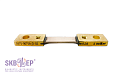
For checking the operability of the device. Value – 1 mΩ ± 0.5%. Manufactured by SKB EP.
Adapter for a reference coil
023.12.00. 000
Adapter for a reference coil
023.12.00. 000
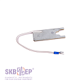
For testing laboratories: inspection / calibration of the instrument (0.024 kg).
Recommended accessories:
Photo
Item, Index
Application
Manipulating rod
010.41.00.000К
Manipulating rod
010.41.00.000К
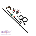
Manipulating rod is designed for test cables connection from the ground or from the tank cover to the bushings of high-voltage circuit breakers, and to the structural elements of high-voltage disconnecting switches and earthing devices, without the use of ladders or elevated platforms.
The manipulating rod is completed with special extension cables 3.3 m. There is a Kelvin clamp with current and potential contacts to connect to the object on one side, and a contact pad on the other side. The device test cable is connected to the contact pad from the ground or a tank cover.
Manipulating rod extension cable is made according to a four-wire (Kelvin) scheme with the test current capacity of 100 A in the presence of a good contact.
Manipulating rod - 2.2 (length 2.2 m / weight as an assembled set 3.4 kg);
Manipulating rod - 3.7 (length 3.7 m / weight as an assembled set 4.0 kg);
Manipulating rod - 5.1 (length 5.1 m / weight as an assembled set 4.6 kg).
Extension cable
010.41.08.000
Extension cable
010.41.08.000
An additional cable set for the manipulating rod's standard complete set, designed for simultaneous connection to 4 high-voltage object bushings.
Manipulating rod's extension cable (0.86 kg) is designed with the 4-wire scheme and has a test current capacity of 50 A.
Official reviews from customers based on the results of operating SKB EP instruments are available upon request. Please, fill out the form on the website.