Array
(
[ID] => 28859
[~ID] => 28859
[NAME] => High precision measurements of DC electrical resistance in the range from 0.1 µΩ to 2 Ω with an accuracy of ±0.05%
[~NAME] => High precision measurements of DC electrical resistance in the range from 0.1 µΩ to 2 Ω with an accuracy of ±0.05%
[IBLOCK_ID] => 102
[~IBLOCK_ID] => 102
[DETAIL_TEXT] =>
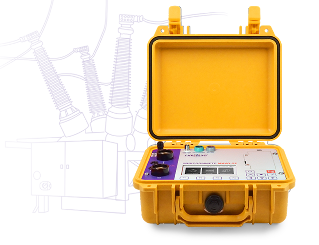
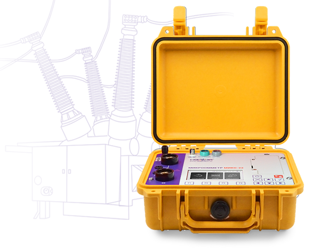
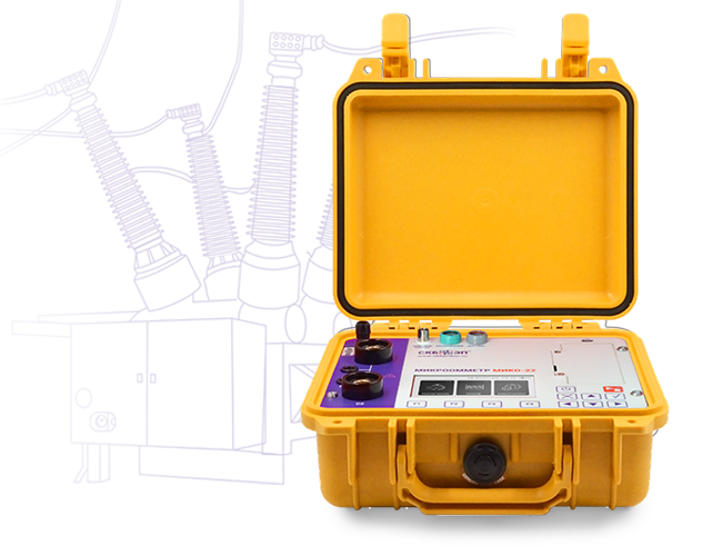
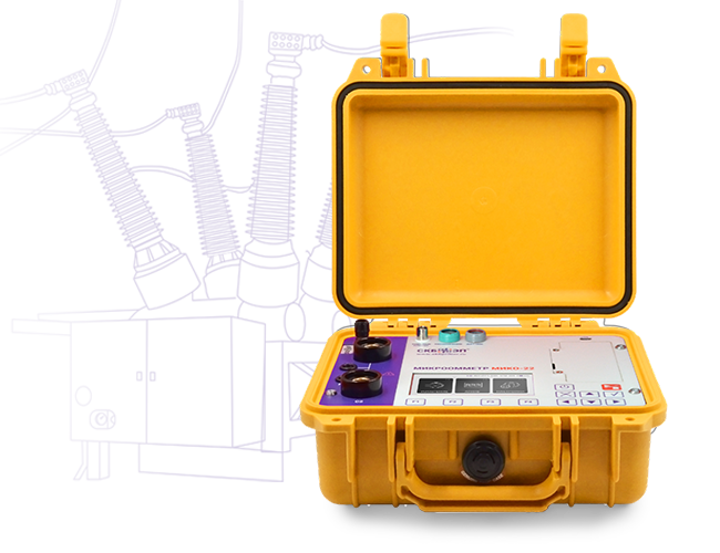
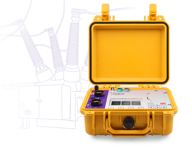
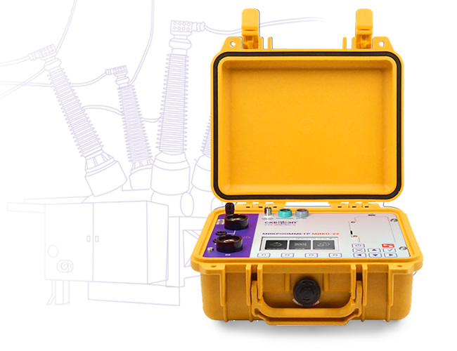
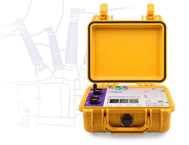
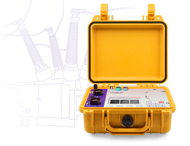
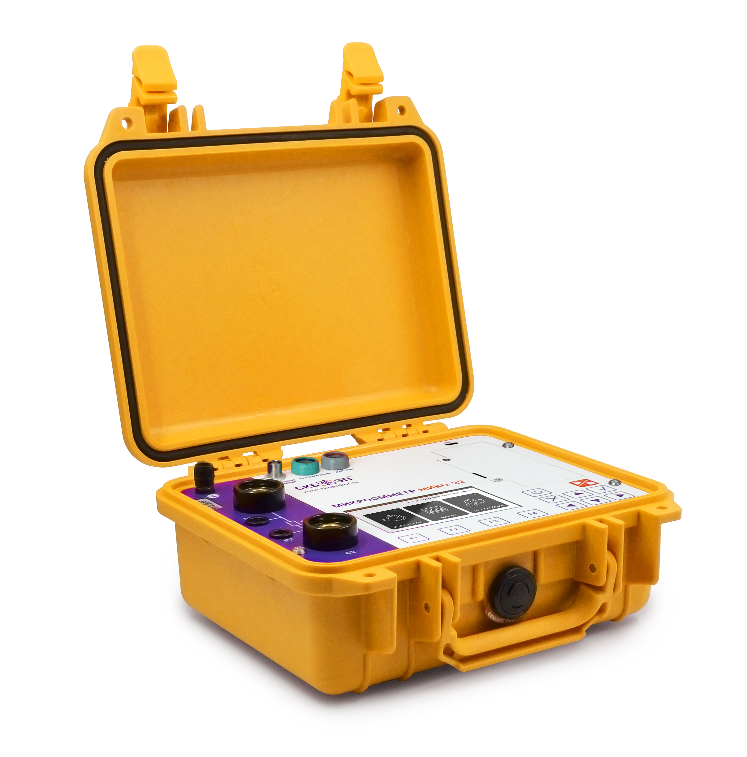
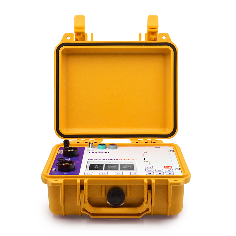
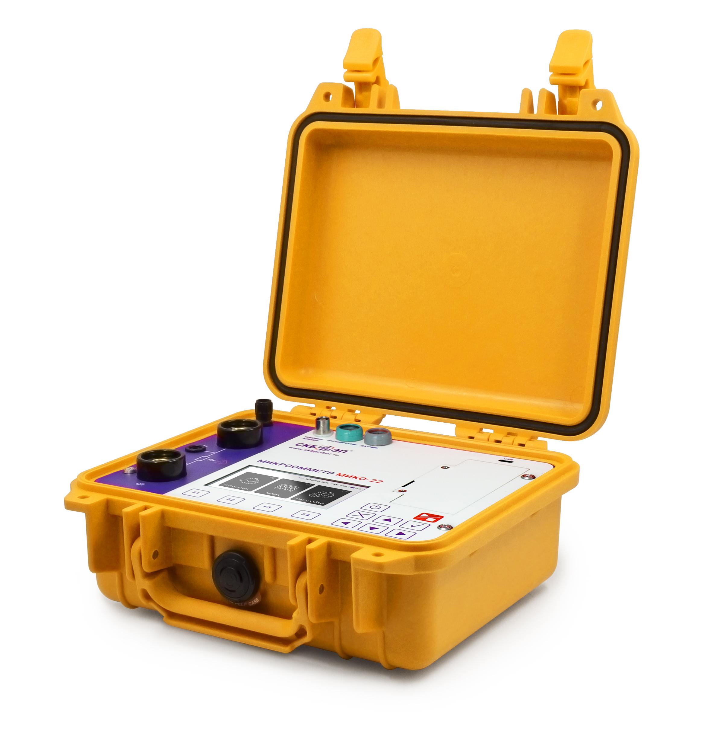
MIKO-22 micro-ohmmeter is based on the time-tested
MIKO-21
instrument with significantly expanded features, including modern electrical resistance measurement methods:
Measurement of DC electrical resistance using the DG (Dual Grounding) method.
Measurement of electrical resistance using the DCRM (Dynamic Contact Resistance Measurement)
method for the main and arcing contacts of high-voltage circuit breaker poles.
The device is designed to measure DC electrical resistance in the range from 0.1 μΩ to 2 Ω at a current of 200 A and can test:
Main contacts of high-voltage circuit breakers of all types and voltage classes.
Arcing contacts of high-voltage circuit breaker poles.
Contactors, relays, disconnectors, and short-circuiters.
Busbars, various bolted connections, welded joints, and brazed joints.
Elements of equipment for open and closed switchgears in extreme electric and magnetic field conditions.
Components of electrical equipment during high-precision measurements in research laboratories and industrial facilities.
MIKO-22
MIKO-21
MIKO-10
MIKO-2.3
Test current
200 A
200 A
10 A
1000 A
Resistance range
0.1 μΩ – 2 Ω
0.1 μΩ – 2 Ω
1 μΩ – 0.1 Ω
1 μΩ – 0.1 Ω
Accuracy
±0.05%
±0.05%
±0.2%
±0.2%
Comparison of results with nominal values
DCRM
DG
Removable battery
[~DETAIL_TEXT] =>
MIKO-22 micro-ohmmeter is based on the time-tested
MIKO-21
instrument with significantly expanded features, including modern electrical resistance measurement methods:
Measurement of DC electrical resistance using the DG (Dual Grounding) method.
Measurement of electrical resistance using the DCRM (Dynamic Contact Resistance Measurement)
method for the main and arcing contacts of high-voltage circuit breaker poles.
The device is designed to measure DC electrical resistance in the range from 0.1 μΩ to 2 Ω at a current of 200 A and can test:
Main contacts of high-voltage circuit breakers of all types and voltage classes.
Arcing contacts of high-voltage circuit breaker poles.
Contactors, relays, disconnectors, and short-circuiters.
Busbars, various bolted connections, welded joints, and brazed joints.
Elements of equipment for open and closed switchgears in extreme electric and magnetic field conditions.
Components of electrical equipment during high-precision measurements in research laboratories and industrial facilities.
MIKO-22
MIKO-21
MIKO-10
MIKO-2.3
Test current
200 A
200 A
10 A
1000 A
Resistance range
0.1 μΩ – 2 Ω
0.1 μΩ – 2 Ω
1 μΩ – 0.1 Ω
1 μΩ – 0.1 Ω
Accuracy
±0.05%
±0.05%
±0.2%
±0.2%
Comparison of results with nominal values
DCRM
DG
Removable battery
[SORT] => 10
[~SORT] => 10
[DETAIL_TEXT_TYPE] => html
[~DETAIL_TEXT_TYPE] => html
[PROPERTIES] => Array
(
[PREVIEW_ICON] => Array
(
[ID] => 310
[TIMESTAMP_X] => 2019-11-18 14:18:31
[IBLOCK_ID] => 102
[NAME] => Иконка для анонса
[ACTIVE] => Y
[SORT] => 500
[CODE] => PREVIEW_ICON
[DEFAULT_VALUE] =>
[PROPERTY_TYPE] => F
[ROW_COUNT] => 1
[COL_COUNT] => 50
[LIST_TYPE] => L
[MULTIPLE] => N
[XML_ID] => 28
[FILE_TYPE] => jpg, png, jpeg
[MULTIPLE_CNT] => 5
[TMP_ID] =>
[LINK_IBLOCK_ID] => 0
[WITH_DESCRIPTION] => N
[SEARCHABLE] => N
[FILTRABLE] => N
[IS_REQUIRED] => Y
[VERSION] => 1
[USER_TYPE] =>
[USER_TYPE_SETTINGS] =>
[HINT] =>
[PROPERTY_VALUE_ID] => 100947
[VALUE] => 42446
[DESCRIPTION] =>
[VALUE_ENUM] =>
[VALUE_XML_ID] =>
[VALUE_SORT] =>
[~VALUE] => 42446
[~DESCRIPTION] =>
[~NAME] => Иконка для анонса
[~DEFAULT_VALUE] =>
)
[DETAIL_ICON] => Array
(
[ID] => 311
[TIMESTAMP_X] => 2019-11-18 14:18:31
[IBLOCK_ID] => 102
[NAME] => Иконка для описания
[ACTIVE] => Y
[SORT] => 500
[CODE] => DETAIL_ICON
[DEFAULT_VALUE] =>
[PROPERTY_TYPE] => F
[ROW_COUNT] => 1
[COL_COUNT] => 50
[LIST_TYPE] => L
[MULTIPLE] => N
[XML_ID] => 29
[FILE_TYPE] => jpg, png, jpeg
[MULTIPLE_CNT] => 5
[TMP_ID] =>
[LINK_IBLOCK_ID] => 0
[WITH_DESCRIPTION] => N
[SEARCHABLE] => N
[FILTRABLE] => N
[IS_REQUIRED] => Y
[VERSION] => 1
[USER_TYPE] =>
[USER_TYPE_SETTINGS] =>
[HINT] =>
[PROPERTY_VALUE_ID] => 100948
[VALUE] => 42447
[DESCRIPTION] =>
[VALUE_ENUM] =>
[VALUE_XML_ID] =>
[VALUE_SORT] =>
[~VALUE] => 42447
[~DESCRIPTION] =>
[~NAME] => Иконка для описания
[~DEFAULT_VALUE] =>
)
[MORE_PHOTO] => Array
(
[ID] => 312
[TIMESTAMP_X] => 2019-11-18 14:18:31
[IBLOCK_ID] => 102
[NAME] => Фотографии
[ACTIVE] => Y
[SORT] => 500
[CODE] => MORE_PHOTO
[DEFAULT_VALUE] =>
[PROPERTY_TYPE] => F
[ROW_COUNT] => 1
[COL_COUNT] => 50
[LIST_TYPE] => L
[MULTIPLE] => Y
[XML_ID] => 30
[FILE_TYPE] => jpg, png, jpeg
[MULTIPLE_CNT] => 5
[TMP_ID] =>
[LINK_IBLOCK_ID] => 0
[WITH_DESCRIPTION] => Y
[SEARCHABLE] => N
[FILTRABLE] => N
[IS_REQUIRED] => N
[VERSION] => 1
[USER_TYPE] =>
[USER_TYPE_SETTINGS] =>
[HINT] =>
[PROPERTY_VALUE_ID] =>
[VALUE] =>
[DESCRIPTION] =>
[VALUE_ENUM] =>
[VALUE_XML_ID] =>
[VALUE_SORT] =>
[~VALUE] =>
[~DESCRIPTION] =>
[~NAME] => Фотографии
[~DEFAULT_VALUE] =>
)
)
)
The instrument supports three modes for starting resistance measurements:
Single – measurement is started once the cable clamps are connected to the tested object and the START button is pressed. The device performs a single measurement and then enters standby mode until the next command is received.
Periodic – used for measurements at predefined intervals. After pressing the START button, the instrument automatically performs measurements according to the selected interval without further user intervention. This mode is particularly useful when the operator's hands are occupied with connecting cables or when monitoring parameter changes over time.
Periodic Circuit – combines automatic activation with periodic measurements when the tested circuit is closed. After pressing the START button, the device waits for the contacts to close before initiating measurements. Measurements continue automatically until the user stops the process.

[~DETAIL_TEXT] =>
The instrument supports three modes for starting resistance measurements:
Single – measurement is started once the cable clamps are connected to the tested object and the START button is pressed. The device performs a single measurement and then enters standby mode until the next command is received.
Periodic – used for measurements at predefined intervals. After pressing the START button, the instrument automatically performs measurements according to the selected interval without further user intervention. This mode is particularly useful when the operator's hands are occupied with connecting cables or when monitoring parameter changes over time.
Periodic Circuit – combines automatic activation with periodic measurements when the tested circuit is closed. After pressing the START button, the device waits for the contacts to close before initiating measurements. Measurements continue automatically until the user stops the process.
[SORT] => 20
[~SORT] => 20
[DETAIL_TEXT_TYPE] => html
[~DETAIL_TEXT_TYPE] => html
[PROPERTIES] => Array
(
[PREVIEW_ICON] => Array
(
[ID] => 310
[TIMESTAMP_X] => 2019-11-18 14:18:31
[IBLOCK_ID] => 102
[NAME] => Иконка для анонса
[ACTIVE] => Y
[SORT] => 500
[CODE] => PREVIEW_ICON
[DEFAULT_VALUE] =>
[PROPERTY_TYPE] => F
[ROW_COUNT] => 1
[COL_COUNT] => 50
[LIST_TYPE] => L
[MULTIPLE] => N
[XML_ID] => 28
[FILE_TYPE] => jpg, png, jpeg
[MULTIPLE_CNT] => 5
[TMP_ID] =>
[LINK_IBLOCK_ID] => 0
[WITH_DESCRIPTION] => N
[SEARCHABLE] => N
[FILTRABLE] => N
[IS_REQUIRED] => Y
[VERSION] => 1
[USER_TYPE] =>
[USER_TYPE_SETTINGS] =>
[HINT] =>
[PROPERTY_VALUE_ID] => 100949
[VALUE] => 42449
[DESCRIPTION] =>
[VALUE_ENUM] =>
[VALUE_XML_ID] =>
[VALUE_SORT] =>
[~VALUE] => 42449
[~DESCRIPTION] =>
[~NAME] => Иконка для анонса
[~DEFAULT_VALUE] =>
)
[DETAIL_ICON] => Array
(
[ID] => 311
[TIMESTAMP_X] => 2019-11-18 14:18:31
[IBLOCK_ID] => 102
[NAME] => Иконка для описания
[ACTIVE] => Y
[SORT] => 500
[CODE] => DETAIL_ICON
[DEFAULT_VALUE] =>
[PROPERTY_TYPE] => F
[ROW_COUNT] => 1
[COL_COUNT] => 50
[LIST_TYPE] => L
[MULTIPLE] => N
[XML_ID] => 29
[FILE_TYPE] => jpg, png, jpeg
[MULTIPLE_CNT] => 5
[TMP_ID] =>
[LINK_IBLOCK_ID] => 0
[WITH_DESCRIPTION] => N
[SEARCHABLE] => N
[FILTRABLE] => N
[IS_REQUIRED] => Y
[VERSION] => 1
[USER_TYPE] =>
[USER_TYPE_SETTINGS] =>
[HINT] =>
[PROPERTY_VALUE_ID] => 100950
[VALUE] => 42450
[DESCRIPTION] =>
[VALUE_ENUM] =>
[VALUE_XML_ID] =>
[VALUE_SORT] =>
[~VALUE] => 42450
[~DESCRIPTION] =>
[~NAME] => Иконка для описания
[~DEFAULT_VALUE] =>
)
[MORE_PHOTO] => Array
(
[ID] => 312
[TIMESTAMP_X] => 2019-11-18 14:18:31
[IBLOCK_ID] => 102
[NAME] => Фотографии
[ACTIVE] => Y
[SORT] => 500
[CODE] => MORE_PHOTO
[DEFAULT_VALUE] =>
[PROPERTY_TYPE] => F
[ROW_COUNT] => 1
[COL_COUNT] => 50
[LIST_TYPE] => L
[MULTIPLE] => Y
[XML_ID] => 30
[FILE_TYPE] => jpg, png, jpeg
[MULTIPLE_CNT] => 5
[TMP_ID] =>
[LINK_IBLOCK_ID] => 0
[WITH_DESCRIPTION] => Y
[SEARCHABLE] => N
[FILTRABLE] => N
[IS_REQUIRED] => N
[VERSION] => 1
[USER_TYPE] =>
[USER_TYPE_SETTINGS] =>
[HINT] =>
[PROPERTY_VALUE_ID] =>
[VALUE] =>
[DESCRIPTION] =>
[VALUE_ENUM] =>
[VALUE_XML_ID] =>
[VALUE_SORT] =>
[~VALUE] =>
[~DESCRIPTION] =>
[~NAME] => Фотографии
[~DEFAULT_VALUE] =>
)
)
)
Array
(
[ID] => 28861
[~ID] => 28861
[NAME] => Modes for measuring contact resistance of HV circuit breakers with built-in current transformers (CT)
[~NAME] => Modes for measuring contact resistance of HV circuit breakers with built-in current transformers (CT)
[IBLOCK_ID] => 102
[~IBLOCK_ID] => 102
[DETAIL_TEXT] =>
SKB EP micro-ohmmeters enable contact resistance measurements of both live tank and dead tank circuit breakers using dedicated automatic modes optimized for each application:
CT Eco Mode – enables measurements in circuits equipped with current transformers (CTs) while minimizing battery power consumption. The standard measurement time is approximately 30 seconds.
CT Max Mode – enables measurements in circuits equipped with current transformers (CTs) using a test current of 100 A or 200 A, as selected by the user, without battery-saving restrictions. This mode provides maximum measurement accuracy with a typical measurement time of approximately 15 seconds.
The special automatic measurement modes of the MIKO-22 prevent subjective operator errors, simplify testing procedures, and increase the number of measurements that can be performed on a single battery charge.
[~DETAIL_TEXT] =>
SKB EP micro-ohmmeters enable contact resistance measurements of both live tank and dead tank circuit breakers using dedicated automatic modes optimized for each application:
CT Eco Mode – enables measurements in circuits equipped with current transformers (CTs) while minimizing battery power consumption. The standard measurement time is approximately 30 seconds.
CT Max Mode – enables measurements in circuits equipped with current transformers (CTs) using a test current of 100 A or 200 A, as selected by the user, without battery-saving restrictions. This mode provides maximum measurement accuracy with a typical measurement time of approximately 15 seconds.
The special automatic measurement modes of the MIKO-22 prevent subjective operator errors, simplify testing procedures, and increase the number of measurements that can be performed on a single battery charge.
[SORT] => 30
[~SORT] => 30
[DETAIL_TEXT_TYPE] => html
[~DETAIL_TEXT_TYPE] => html
[PROPERTIES] => Array
(
[PREVIEW_ICON] => Array
(
[ID] => 310
[TIMESTAMP_X] => 2019-11-18 14:18:31
[IBLOCK_ID] => 102
[NAME] => Иконка для анонса
[ACTIVE] => Y
[SORT] => 500
[CODE] => PREVIEW_ICON
[DEFAULT_VALUE] =>
[PROPERTY_TYPE] => F
[ROW_COUNT] => 1
[COL_COUNT] => 50
[LIST_TYPE] => L
[MULTIPLE] => N
[XML_ID] => 28
[FILE_TYPE] => jpg, png, jpeg
[MULTIPLE_CNT] => 5
[TMP_ID] =>
[LINK_IBLOCK_ID] => 0
[WITH_DESCRIPTION] => N
[SEARCHABLE] => N
[FILTRABLE] => N
[IS_REQUIRED] => Y
[VERSION] => 1
[USER_TYPE] =>
[USER_TYPE_SETTINGS] =>
[HINT] =>
[PROPERTY_VALUE_ID] => 100951
[VALUE] => 42452
[DESCRIPTION] =>
[VALUE_ENUM] =>
[VALUE_XML_ID] =>
[VALUE_SORT] =>
[~VALUE] => 42452
[~DESCRIPTION] =>
[~NAME] => Иконка для анонса
[~DEFAULT_VALUE] =>
)
[DETAIL_ICON] => Array
(
[ID] => 311
[TIMESTAMP_X] => 2019-11-18 14:18:31
[IBLOCK_ID] => 102
[NAME] => Иконка для описания
[ACTIVE] => Y
[SORT] => 500
[CODE] => DETAIL_ICON
[DEFAULT_VALUE] =>
[PROPERTY_TYPE] => F
[ROW_COUNT] => 1
[COL_COUNT] => 50
[LIST_TYPE] => L
[MULTIPLE] => N
[XML_ID] => 29
[FILE_TYPE] => jpg, png, jpeg
[MULTIPLE_CNT] => 5
[TMP_ID] =>
[LINK_IBLOCK_ID] => 0
[WITH_DESCRIPTION] => N
[SEARCHABLE] => N
[FILTRABLE] => N
[IS_REQUIRED] => Y
[VERSION] => 1
[USER_TYPE] =>
[USER_TYPE_SETTINGS] =>
[HINT] =>
[PROPERTY_VALUE_ID] => 100952
[VALUE] => 42453
[DESCRIPTION] =>
[VALUE_ENUM] =>
[VALUE_XML_ID] =>
[VALUE_SORT] =>
[~VALUE] => 42453
[~DESCRIPTION] =>
[~NAME] => Иконка для описания
[~DEFAULT_VALUE] =>
)
[MORE_PHOTO] => Array
(
[ID] => 312
[TIMESTAMP_X] => 2019-11-18 14:18:31
[IBLOCK_ID] => 102
[NAME] => Фотографии
[ACTIVE] => Y
[SORT] => 500
[CODE] => MORE_PHOTO
[DEFAULT_VALUE] =>
[PROPERTY_TYPE] => F
[ROW_COUNT] => 1
[COL_COUNT] => 50
[LIST_TYPE] => L
[MULTIPLE] => Y
[XML_ID] => 30
[FILE_TYPE] => jpg, png, jpeg
[MULTIPLE_CNT] => 5
[TMP_ID] =>
[LINK_IBLOCK_ID] => 0
[WITH_DESCRIPTION] => Y
[SEARCHABLE] => N
[FILTRABLE] => N
[IS_REQUIRED] => N
[VERSION] => 1
[USER_TYPE] =>
[USER_TYPE_SETTINGS] =>
[HINT] =>
[PROPERTY_VALUE_ID] =>
[VALUE] =>
[DESCRIPTION] =>
[VALUE_ENUM] =>
[VALUE_XML_ID] =>
[VALUE_SORT] =>
[~VALUE] =>
[~DESCRIPTION] =>
[~NAME] => Фотографии
[~DEFAULT_VALUE] =>
)
)
)
Array
(
[ID] => 28862
[~ID] => 28862
[NAME] => Adjustable test current up to 200 A
[~NAME] => Adjustable test current up to 200 A
[IBLOCK_ID] => 102
[~IBLOCK_ID] => 102
[DETAIL_TEXT] =>
MIKO-22 provides quick and convenient selection of test current values up to 200 A. The required test current can be configured using one of the following methods:
Selection from predefined current values: 10 A, 50 A, 100 A, and 200 A.
Selection of the Automatic Test Current mode.
Selection of the Manual Test Current mode, allowing current adjustment from 1 A to 200 A with a resolution of 1 A.
This flexible approach allows measurements to be quickly adapted to the requirements of a specific application, ensuring both efficiency and accuracy during testing.
[~DETAIL_TEXT] =>
MIKO-22 provides quick and convenient selection of test current values up to 200 A. The required test current can be configured using one of the following methods:
Selection from predefined current values: 10 A, 50 A, 100 A, and 200 A.
Selection of the Automatic Test Current mode.
Selection of the Manual Test Current mode, allowing current adjustment from 1 A to 200 A with a resolution of 1 A.
This flexible approach allows measurements to be quickly adapted to the requirements of a specific application, ensuring both efficiency and accuracy during testing.
[SORT] => 40
[~SORT] => 40
[DETAIL_TEXT_TYPE] => html
[~DETAIL_TEXT_TYPE] => html
[PROPERTIES] => Array
(
[PREVIEW_ICON] => Array
(
[ID] => 310
[TIMESTAMP_X] => 2019-11-18 14:18:31
[IBLOCK_ID] => 102
[NAME] => Иконка для анонса
[ACTIVE] => Y
[SORT] => 500
[CODE] => PREVIEW_ICON
[DEFAULT_VALUE] =>
[PROPERTY_TYPE] => F
[ROW_COUNT] => 1
[COL_COUNT] => 50
[LIST_TYPE] => L
[MULTIPLE] => N
[XML_ID] => 28
[FILE_TYPE] => jpg, png, jpeg
[MULTIPLE_CNT] => 5
[TMP_ID] =>
[LINK_IBLOCK_ID] => 0
[WITH_DESCRIPTION] => N
[SEARCHABLE] => N
[FILTRABLE] => N
[IS_REQUIRED] => Y
[VERSION] => 1
[USER_TYPE] =>
[USER_TYPE_SETTINGS] =>
[HINT] =>
[PROPERTY_VALUE_ID] => 100953
[VALUE] => 42455
[DESCRIPTION] =>
[VALUE_ENUM] =>
[VALUE_XML_ID] =>
[VALUE_SORT] =>
[~VALUE] => 42455
[~DESCRIPTION] =>
[~NAME] => Иконка для анонса
[~DEFAULT_VALUE] =>
)
[DETAIL_ICON] => Array
(
[ID] => 311
[TIMESTAMP_X] => 2019-11-18 14:18:31
[IBLOCK_ID] => 102
[NAME] => Иконка для описания
[ACTIVE] => Y
[SORT] => 500
[CODE] => DETAIL_ICON
[DEFAULT_VALUE] =>
[PROPERTY_TYPE] => F
[ROW_COUNT] => 1
[COL_COUNT] => 50
[LIST_TYPE] => L
[MULTIPLE] => N
[XML_ID] => 29
[FILE_TYPE] => jpg, png, jpeg
[MULTIPLE_CNT] => 5
[TMP_ID] =>
[LINK_IBLOCK_ID] => 0
[WITH_DESCRIPTION] => N
[SEARCHABLE] => N
[FILTRABLE] => N
[IS_REQUIRED] => Y
[VERSION] => 1
[USER_TYPE] =>
[USER_TYPE_SETTINGS] =>
[HINT] =>
[PROPERTY_VALUE_ID] => 100954
[VALUE] => 42456
[DESCRIPTION] =>
[VALUE_ENUM] =>
[VALUE_XML_ID] =>
[VALUE_SORT] =>
[~VALUE] => 42456
[~DESCRIPTION] =>
[~NAME] => Иконка для описания
[~DEFAULT_VALUE] =>
)
[MORE_PHOTO] => Array
(
[ID] => 312
[TIMESTAMP_X] => 2019-11-18 14:18:31
[IBLOCK_ID] => 102
[NAME] => Фотографии
[ACTIVE] => Y
[SORT] => 500
[CODE] => MORE_PHOTO
[DEFAULT_VALUE] =>
[PROPERTY_TYPE] => F
[ROW_COUNT] => 1
[COL_COUNT] => 50
[LIST_TYPE] => L
[MULTIPLE] => Y
[XML_ID] => 30
[FILE_TYPE] => jpg, png, jpeg
[MULTIPLE_CNT] => 5
[TMP_ID] =>
[LINK_IBLOCK_ID] => 0
[WITH_DESCRIPTION] => Y
[SEARCHABLE] => N
[FILTRABLE] => N
[IS_REQUIRED] => N
[VERSION] => 1
[USER_TYPE] =>
[USER_TYPE_SETTINGS] =>
[HINT] =>
[PROPERTY_VALUE_ID] =>
[VALUE] =>
[DESCRIPTION] =>
[VALUE_ENUM] =>
[VALUE_XML_ID] =>
[VALUE_SORT] =>
[~VALUE] =>
[~DESCRIPTION] =>
[~NAME] => Фотографии
[~DEFAULT_VALUE] =>
)
)
)
Array
(
[ID] => 28863
[~ID] => 28863
[NAME] => Measurement of DC electrical resistance using the DG method
[~NAME] => Measurement of DC electrical resistance using the DG method
[IBLOCK_ID] => 102
[~IBLOCK_ID] => 102
[DETAIL_TEXT] =>
The DG (Dual Grounding) method is designed for measuring the resistance of parallel conductive paths. Such paths are typically present when a high-voltage circuit breaker is disconnected and grounded on both sides to ensure personnel safety during maintenance work.
When conventional micro-ohmmeters are used to measure contact resistance, one side of the circuit breaker must be disconnected from ground, which reduces operational safety. The DG method enables resistance measurements to be performed without removing the grounding connection, ensuring both safe and accurate testing.
The DG method utilizes an additional measurement channel with current clamps to determine the current flowing through a parallel conductive path of the circuit breaker's main contacts.
[~DETAIL_TEXT] =>
The DG (Dual Grounding) method is designed for measuring the resistance of parallel conductive paths. Such paths are typically present when a high-voltage circuit breaker is disconnected and grounded on both sides to ensure personnel safety during maintenance work.
When conventional micro-ohmmeters are used to measure contact resistance, one side of the circuit breaker must be disconnected from ground, which reduces operational safety. The DG method enables resistance measurements to be performed without removing the grounding connection, ensuring both safe and accurate testing.
The DG method utilizes an additional measurement channel with current clamps to determine the current flowing through a parallel conductive path of the circuit breaker's main contacts.
[SORT] => 50
[~SORT] => 50
[DETAIL_TEXT_TYPE] => html
[~DETAIL_TEXT_TYPE] => html
[PROPERTIES] => Array
(
[PREVIEW_ICON] => Array
(
[ID] => 310
[TIMESTAMP_X] => 2019-11-18 14:18:31
[IBLOCK_ID] => 102
[NAME] => Иконка для анонса
[ACTIVE] => Y
[SORT] => 500
[CODE] => PREVIEW_ICON
[DEFAULT_VALUE] =>
[PROPERTY_TYPE] => F
[ROW_COUNT] => 1
[COL_COUNT] => 50
[LIST_TYPE] => L
[MULTIPLE] => N
[XML_ID] => 28
[FILE_TYPE] => jpg, png, jpeg
[MULTIPLE_CNT] => 5
[TMP_ID] =>
[LINK_IBLOCK_ID] => 0
[WITH_DESCRIPTION] => N
[SEARCHABLE] => N
[FILTRABLE] => N
[IS_REQUIRED] => Y
[VERSION] => 1
[USER_TYPE] =>
[USER_TYPE_SETTINGS] =>
[HINT] =>
[PROPERTY_VALUE_ID] => 100955
[VALUE] => 42458
[DESCRIPTION] =>
[VALUE_ENUM] =>
[VALUE_XML_ID] =>
[VALUE_SORT] =>
[~VALUE] => 42458
[~DESCRIPTION] =>
[~NAME] => Иконка для анонса
[~DEFAULT_VALUE] =>
)
[DETAIL_ICON] => Array
(
[ID] => 311
[TIMESTAMP_X] => 2019-11-18 14:18:31
[IBLOCK_ID] => 102
[NAME] => Иконка для описания
[ACTIVE] => Y
[SORT] => 500
[CODE] => DETAIL_ICON
[DEFAULT_VALUE] =>
[PROPERTY_TYPE] => F
[ROW_COUNT] => 1
[COL_COUNT] => 50
[LIST_TYPE] => L
[MULTIPLE] => N
[XML_ID] => 29
[FILE_TYPE] => jpg, png, jpeg
[MULTIPLE_CNT] => 5
[TMP_ID] =>
[LINK_IBLOCK_ID] => 0
[WITH_DESCRIPTION] => N
[SEARCHABLE] => N
[FILTRABLE] => N
[IS_REQUIRED] => Y
[VERSION] => 1
[USER_TYPE] =>
[USER_TYPE_SETTINGS] =>
[HINT] =>
[PROPERTY_VALUE_ID] => 100956
[VALUE] => 42459
[DESCRIPTION] =>
[VALUE_ENUM] =>
[VALUE_XML_ID] =>
[VALUE_SORT] =>
[~VALUE] => 42459
[~DESCRIPTION] =>
[~NAME] => Иконка для описания
[~DEFAULT_VALUE] =>
)
[MORE_PHOTO] => Array
(
[ID] => 312
[TIMESTAMP_X] => 2019-11-18 14:18:31
[IBLOCK_ID] => 102
[NAME] => Фотографии
[ACTIVE] => Y
[SORT] => 500
[CODE] => MORE_PHOTO
[DEFAULT_VALUE] =>
[PROPERTY_TYPE] => F
[ROW_COUNT] => 1
[COL_COUNT] => 50
[LIST_TYPE] => L
[MULTIPLE] => Y
[XML_ID] => 30
[FILE_TYPE] => jpg, png, jpeg
[MULTIPLE_CNT] => 5
[TMP_ID] =>
[LINK_IBLOCK_ID] => 0
[WITH_DESCRIPTION] => Y
[SEARCHABLE] => N
[FILTRABLE] => N
[IS_REQUIRED] => N
[VERSION] => 1
[USER_TYPE] =>
[USER_TYPE_SETTINGS] =>
[HINT] =>
[PROPERTY_VALUE_ID] =>
[VALUE] =>
[DESCRIPTION] =>
[VALUE_ENUM] =>
[VALUE_XML_ID] =>
[VALUE_SORT] =>
[~VALUE] =>
[~DESCRIPTION] =>
[~NAME] => Фотографии
[~DEFAULT_VALUE] =>
)
)
)
Array
(
[ID] => 28864
[~ID] => 28864
[NAME] => Measurement of DC electrical resistance using the DCRM method
[~NAME] => Measurement of DC electrical resistance using the DCRM method
[IBLOCK_ID] => 102
[~IBLOCK_ID] => 102
[DETAIL_TEXT] =>
MIKO-22 is equipped with a DCRM (Dynamic Contact Resistance Measurement)
mode that allows the condition of a high-voltage circuit breaker’s contacts to be assessed
without disassembly. The method provides effective monitoring of both main and arcing contacts
by recording resistance changes during the circuit breaker opening operation.
Additional Features
High-Voltage Circuit Breaker Drive Control – the integrated drive control
function simplifies and improves the convenience of DCRM measurements.
Linear and Angular Displacement Measurement – enables mechanical parameters
of the circuit breaker to be recorded simultaneously with resistance measurements, allowing
evaluation of the remaining arcing contact length.
Linear displacement range: 1–900 mm
Angular displacement range: 0.09–360°
[~DETAIL_TEXT] =>
MIKO-22 is equipped with a DCRM (Dynamic Contact Resistance Measurement)
mode that allows the condition of a high-voltage circuit breaker’s contacts to be assessed
without disassembly. The method provides effective monitoring of both main and arcing contacts
by recording resistance changes during the circuit breaker opening operation.
Additional Features
High-Voltage Circuit Breaker Drive Control – the integrated drive control
function simplifies and improves the convenience of DCRM measurements.
Linear and Angular Displacement Measurement – enables mechanical parameters
of the circuit breaker to be recorded simultaneously with resistance measurements, allowing
evaluation of the remaining arcing contact length.
Linear displacement range: 1–900 mm
Angular displacement range: 0.09–360°
[SORT] => 60
[~SORT] => 60
[DETAIL_TEXT_TYPE] => html
[~DETAIL_TEXT_TYPE] => html
[PROPERTIES] => Array
(
[PREVIEW_ICON] => Array
(
[ID] => 310
[TIMESTAMP_X] => 2019-11-18 14:18:31
[IBLOCK_ID] => 102
[NAME] => Иконка для анонса
[ACTIVE] => Y
[SORT] => 500
[CODE] => PREVIEW_ICON
[DEFAULT_VALUE] =>
[PROPERTY_TYPE] => F
[ROW_COUNT] => 1
[COL_COUNT] => 50
[LIST_TYPE] => L
[MULTIPLE] => N
[XML_ID] => 28
[FILE_TYPE] => jpg, png, jpeg
[MULTIPLE_CNT] => 5
[TMP_ID] =>
[LINK_IBLOCK_ID] => 0
[WITH_DESCRIPTION] => N
[SEARCHABLE] => N
[FILTRABLE] => N
[IS_REQUIRED] => Y
[VERSION] => 1
[USER_TYPE] =>
[USER_TYPE_SETTINGS] =>
[HINT] =>
[PROPERTY_VALUE_ID] => 100957
[VALUE] => 42461
[DESCRIPTION] =>
[VALUE_ENUM] =>
[VALUE_XML_ID] =>
[VALUE_SORT] =>
[~VALUE] => 42461
[~DESCRIPTION] =>
[~NAME] => Иконка для анонса
[~DEFAULT_VALUE] =>
)
[DETAIL_ICON] => Array
(
[ID] => 311
[TIMESTAMP_X] => 2019-11-18 14:18:31
[IBLOCK_ID] => 102
[NAME] => Иконка для описания
[ACTIVE] => Y
[SORT] => 500
[CODE] => DETAIL_ICON
[DEFAULT_VALUE] =>
[PROPERTY_TYPE] => F
[ROW_COUNT] => 1
[COL_COUNT] => 50
[LIST_TYPE] => L
[MULTIPLE] => N
[XML_ID] => 29
[FILE_TYPE] => jpg, png, jpeg
[MULTIPLE_CNT] => 5
[TMP_ID] =>
[LINK_IBLOCK_ID] => 0
[WITH_DESCRIPTION] => N
[SEARCHABLE] => N
[FILTRABLE] => N
[IS_REQUIRED] => Y
[VERSION] => 1
[USER_TYPE] =>
[USER_TYPE_SETTINGS] =>
[HINT] =>
[PROPERTY_VALUE_ID] => 100958
[VALUE] => 42462
[DESCRIPTION] =>
[VALUE_ENUM] =>
[VALUE_XML_ID] =>
[VALUE_SORT] =>
[~VALUE] => 42462
[~DESCRIPTION] =>
[~NAME] => Иконка для описания
[~DEFAULT_VALUE] =>
)
[MORE_PHOTO] => Array
(
[ID] => 312
[TIMESTAMP_X] => 2019-11-18 14:18:31
[IBLOCK_ID] => 102
[NAME] => Фотографии
[ACTIVE] => Y
[SORT] => 500
[CODE] => MORE_PHOTO
[DEFAULT_VALUE] =>
[PROPERTY_TYPE] => F
[ROW_COUNT] => 1
[COL_COUNT] => 50
[LIST_TYPE] => L
[MULTIPLE] => Y
[XML_ID] => 30
[FILE_TYPE] => jpg, png, jpeg
[MULTIPLE_CNT] => 5
[TMP_ID] =>
[LINK_IBLOCK_ID] => 0
[WITH_DESCRIPTION] => Y
[SEARCHABLE] => N
[FILTRABLE] => N
[IS_REQUIRED] => N
[VERSION] => 1
[USER_TYPE] =>
[USER_TYPE_SETTINGS] =>
[HINT] =>
[PROPERTY_VALUE_ID] =>
[VALUE] =>
[DESCRIPTION] =>
[VALUE_ENUM] =>
[VALUE_XML_ID] =>
[VALUE_SORT] =>
[~VALUE] =>
[~DESCRIPTION] =>
[~NAME] => Фотографии
[~DEFAULT_VALUE] =>
)
)
)
Array
(
[ID] => 28865
[~ID] => 28865
[NAME] => Comparison of the results obtained
[~NAME] => Comparison of the results obtained
[IBLOCK_ID] => 102
[~IBLOCK_ID] => 102
[DETAIL_TEXT] =>
The user can add or remove nominal values for the measured object. Once the measured value exceeds the nominal value, the device emits a warning signal and displays an indication that the reading is above/below the set value.
[~DETAIL_TEXT] =>
The user can add or remove nominal values for the measured object. Once the measured value exceeds the nominal value, the device emits a warning signal and displays an indication that the reading is above/below the set value.
[SORT] => 70
[~SORT] => 70
[DETAIL_TEXT_TYPE] => html
[~DETAIL_TEXT_TYPE] => html
[PROPERTIES] => Array
(
[PREVIEW_ICON] => Array
(
[ID] => 310
[TIMESTAMP_X] => 2019-11-18 14:18:31
[IBLOCK_ID] => 102
[NAME] => Иконка для анонса
[ACTIVE] => Y
[SORT] => 500
[CODE] => PREVIEW_ICON
[DEFAULT_VALUE] =>
[PROPERTY_TYPE] => F
[ROW_COUNT] => 1
[COL_COUNT] => 50
[LIST_TYPE] => L
[MULTIPLE] => N
[XML_ID] => 28
[FILE_TYPE] => jpg, png, jpeg
[MULTIPLE_CNT] => 5
[TMP_ID] =>
[LINK_IBLOCK_ID] => 0
[WITH_DESCRIPTION] => N
[SEARCHABLE] => N
[FILTRABLE] => N
[IS_REQUIRED] => Y
[VERSION] => 1
[USER_TYPE] =>
[USER_TYPE_SETTINGS] =>
[HINT] =>
[PROPERTY_VALUE_ID] => 100959
[VALUE] => 42464
[DESCRIPTION] =>
[VALUE_ENUM] =>
[VALUE_XML_ID] =>
[VALUE_SORT] =>
[~VALUE] => 42464
[~DESCRIPTION] =>
[~NAME] => Иконка для анонса
[~DEFAULT_VALUE] =>
)
[DETAIL_ICON] => Array
(
[ID] => 311
[TIMESTAMP_X] => 2019-11-18 14:18:31
[IBLOCK_ID] => 102
[NAME] => Иконка для описания
[ACTIVE] => Y
[SORT] => 500
[CODE] => DETAIL_ICON
[DEFAULT_VALUE] =>
[PROPERTY_TYPE] => F
[ROW_COUNT] => 1
[COL_COUNT] => 50
[LIST_TYPE] => L
[MULTIPLE] => N
[XML_ID] => 29
[FILE_TYPE] => jpg, png, jpeg
[MULTIPLE_CNT] => 5
[TMP_ID] =>
[LINK_IBLOCK_ID] => 0
[WITH_DESCRIPTION] => N
[SEARCHABLE] => N
[FILTRABLE] => N
[IS_REQUIRED] => Y
[VERSION] => 1
[USER_TYPE] =>
[USER_TYPE_SETTINGS] =>
[HINT] =>
[PROPERTY_VALUE_ID] => 100960
[VALUE] => 42465
[DESCRIPTION] =>
[VALUE_ENUM] =>
[VALUE_XML_ID] =>
[VALUE_SORT] =>
[~VALUE] => 42465
[~DESCRIPTION] =>
[~NAME] => Иконка для описания
[~DEFAULT_VALUE] =>
)
[MORE_PHOTO] => Array
(
[ID] => 312
[TIMESTAMP_X] => 2019-11-18 14:18:31
[IBLOCK_ID] => 102
[NAME] => Фотографии
[ACTIVE] => Y
[SORT] => 500
[CODE] => MORE_PHOTO
[DEFAULT_VALUE] =>
[PROPERTY_TYPE] => F
[ROW_COUNT] => 1
[COL_COUNT] => 50
[LIST_TYPE] => L
[MULTIPLE] => Y
[XML_ID] => 30
[FILE_TYPE] => jpg, png, jpeg
[MULTIPLE_CNT] => 5
[TMP_ID] =>
[LINK_IBLOCK_ID] => 0
[WITH_DESCRIPTION] => Y
[SEARCHABLE] => N
[FILTRABLE] => N
[IS_REQUIRED] => N
[VERSION] => 1
[USER_TYPE] =>
[USER_TYPE_SETTINGS] =>
[HINT] =>
[PROPERTY_VALUE_ID] =>
[VALUE] =>
[DESCRIPTION] =>
[VALUE_ENUM] =>
[VALUE_XML_ID] =>
[VALUE_SORT] =>
[~VALUE] =>
[~DESCRIPTION] =>
[~NAME] => Фотографии
[~DEFAULT_VALUE] =>
)
)
)
Array
(
[ID] => 28866
[~ID] => 28866
[NAME] => Built-in battery, portability and data transfer
[~NAME] => Built-in battery, portability and data transfer
[IBLOCK_ID] => 102
[~IBLOCK_ID] => 102
[DETAIL_TEXT] =>
The built-in 100 Wh battery ensures continuous operation without recharging. An optional battery pack allows users to extend the operating time and replace the battery once the main battery has reached the end of its service life.
Special PC software (currently under development) allows users to control the device and transfer measurement results via USB.
[~DETAIL_TEXT] =>
The built-in 100 Wh battery ensures continuous operation without recharging. An optional battery pack allows users to extend the operating time and replace the battery once the main battery has reached the end of its service life.
Special PC software (currently under development) allows users to control the device and transfer measurement results via USB.
[SORT] => 80
[~SORT] => 80
[DETAIL_TEXT_TYPE] => html
[~DETAIL_TEXT_TYPE] => html
[PROPERTIES] => Array
(
[PREVIEW_ICON] => Array
(
[ID] => 310
[TIMESTAMP_X] => 2019-11-18 14:18:31
[IBLOCK_ID] => 102
[NAME] => Иконка для анонса
[ACTIVE] => Y
[SORT] => 500
[CODE] => PREVIEW_ICON
[DEFAULT_VALUE] =>
[PROPERTY_TYPE] => F
[ROW_COUNT] => 1
[COL_COUNT] => 50
[LIST_TYPE] => L
[MULTIPLE] => N
[XML_ID] => 28
[FILE_TYPE] => jpg, png, jpeg
[MULTIPLE_CNT] => 5
[TMP_ID] =>
[LINK_IBLOCK_ID] => 0
[WITH_DESCRIPTION] => N
[SEARCHABLE] => N
[FILTRABLE] => N
[IS_REQUIRED] => Y
[VERSION] => 1
[USER_TYPE] =>
[USER_TYPE_SETTINGS] =>
[HINT] =>
[PROPERTY_VALUE_ID] => 100961
[VALUE] => 42467
[DESCRIPTION] =>
[VALUE_ENUM] =>
[VALUE_XML_ID] =>
[VALUE_SORT] =>
[~VALUE] => 42467
[~DESCRIPTION] =>
[~NAME] => Иконка для анонса
[~DEFAULT_VALUE] =>
)
[DETAIL_ICON] => Array
(
[ID] => 311
[TIMESTAMP_X] => 2019-11-18 14:18:31
[IBLOCK_ID] => 102
[NAME] => Иконка для описания
[ACTIVE] => Y
[SORT] => 500
[CODE] => DETAIL_ICON
[DEFAULT_VALUE] =>
[PROPERTY_TYPE] => F
[ROW_COUNT] => 1
[COL_COUNT] => 50
[LIST_TYPE] => L
[MULTIPLE] => N
[XML_ID] => 29
[FILE_TYPE] => jpg, png, jpeg
[MULTIPLE_CNT] => 5
[TMP_ID] =>
[LINK_IBLOCK_ID] => 0
[WITH_DESCRIPTION] => N
[SEARCHABLE] => N
[FILTRABLE] => N
[IS_REQUIRED] => Y
[VERSION] => 1
[USER_TYPE] =>
[USER_TYPE_SETTINGS] =>
[HINT] =>
[PROPERTY_VALUE_ID] => 100962
[VALUE] => 42468
[DESCRIPTION] =>
[VALUE_ENUM] =>
[VALUE_XML_ID] =>
[VALUE_SORT] =>
[~VALUE] => 42468
[~DESCRIPTION] =>
[~NAME] => Иконка для описания
[~DEFAULT_VALUE] =>
)
[MORE_PHOTO] => Array
(
[ID] => 312
[TIMESTAMP_X] => 2019-11-18 14:18:31
[IBLOCK_ID] => 102
[NAME] => Фотографии
[ACTIVE] => Y
[SORT] => 500
[CODE] => MORE_PHOTO
[DEFAULT_VALUE] =>
[PROPERTY_TYPE] => F
[ROW_COUNT] => 1
[COL_COUNT] => 50
[LIST_TYPE] => L
[MULTIPLE] => Y
[XML_ID] => 30
[FILE_TYPE] => jpg, png, jpeg
[MULTIPLE_CNT] => 5
[TMP_ID] =>
[LINK_IBLOCK_ID] => 0
[WITH_DESCRIPTION] => Y
[SEARCHABLE] => N
[FILTRABLE] => N
[IS_REQUIRED] => N
[VERSION] => 1
[USER_TYPE] =>
[USER_TYPE_SETTINGS] =>
[HINT] =>
[PROPERTY_VALUE_ID] =>
[VALUE] =>
[DESCRIPTION] =>
[VALUE_ENUM] =>
[VALUE_XML_ID] =>
[VALUE_SORT] =>
[~VALUE] =>
[~DESCRIPTION] =>
[~NAME] => Фотографии
[~DEFAULT_VALUE] =>
)
)
)
MIKO-22 micro-ohmmeter is based on the time-tested
MIKO-21
instrument with significantly expanded features, including modern electrical resistance measurement methods:
Measurement of DC electrical resistance using the DG (Dual Grounding) method.
Measurement of electrical resistance using the DCRM (Dynamic Contact Resistance Measurement)
method for the main and arcing contacts of high-voltage circuit breaker poles.
The device is designed to measure DC electrical resistance in the range from 0.1 μΩ to 2 Ω at a current of 200 A and can test:
Main contacts of high-voltage circuit breakers of all types and voltage classes.
Arcing contacts of high-voltage circuit breaker poles.
Contactors, relays, disconnectors, and short-circuiters.
Busbars, various bolted connections, welded joints, and brazed joints.
Elements of equipment for open and closed switchgears in extreme electric and magnetic field conditions.
Components of electrical equipment during high-precision measurements in research laboratories and industrial facilities.
MIKO-22
MIKO-21
MIKO-10
MIKO-2.3
Test current
200 A
200 A
10 A
1000 A
Resistance range
0.1 μΩ – 2 Ω
0.1 μΩ – 2 Ω
1 μΩ – 0.1 Ω
1 μΩ – 0.1 Ω
Accuracy
±0.05%
±0.05%
±0.2%
±0.2%
Comparison of results with nominal values
DCRM
DG
Removable battery
The instrument supports three modes for starting resistance measurements:
Single – measurement is started once the cable clamps are connected to the tested object and the START button is pressed. The device performs a single measurement and then enters standby mode until the next command is received.
Periodic – used for measurements at predefined intervals. After pressing the START button, the instrument automatically performs measurements according to the selected interval without further user intervention. This mode is particularly useful when the operator's hands are occupied with connecting cables or when monitoring parameter changes over time.
Periodic Circuit – combines automatic activation with periodic measurements when the tested circuit is closed. After pressing the START button, the device waits for the contacts to close before initiating measurements. Measurements continue automatically until the user stops the process.
SKB EP micro-ohmmeters enable contact resistance measurements of both live tank and dead tank circuit breakers using dedicated automatic modes optimized for each application:
CT Eco Mode – enables measurements in circuits equipped with current transformers (CTs) while minimizing battery power consumption. The standard measurement time is approximately 30 seconds.
CT Max Mode – enables measurements in circuits equipped with current transformers (CTs) using a test current of 100 A or 200 A, as selected by the user, without battery-saving restrictions. This mode provides maximum measurement accuracy with a typical measurement time of approximately 15 seconds.
The special automatic measurement modes of the MIKO-22 prevent subjective operator errors, simplify testing procedures, and increase the number of measurements that can be performed on a single battery charge.
MIKO-22 provides quick and convenient selection of test current values up to 200 A. The required test current can be configured using one of the following methods:
Selection from predefined current values: 10 A, 50 A, 100 A, and 200 A.
Selection of the Automatic Test Current mode.
Selection of the Manual Test Current mode, allowing current adjustment from 1 A to 200 A with a resolution of 1 A.
This flexible approach allows measurements to be quickly adapted to the requirements of a specific application, ensuring both efficiency and accuracy during testing.
The DG (Dual Grounding) method is designed for measuring the resistance of parallel conductive paths. Such paths are typically present when a high-voltage circuit breaker is disconnected and grounded on both sides to ensure personnel safety during maintenance work.
When conventional micro-ohmmeters are used to measure contact resistance, one side of the circuit breaker must be disconnected from ground, which reduces operational safety. The DG method enables resistance measurements to be performed without removing the grounding connection, ensuring both safe and accurate testing.
The DG method utilizes an additional measurement channel with current clamps to determine the current flowing through a parallel conductive path of the circuit breaker's main contacts.
MIKO-22 is equipped with a DCRM (Dynamic Contact Resistance Measurement)
mode that allows the condition of a high-voltage circuit breaker’s contacts to be assessed
without disassembly. The method provides effective monitoring of both main and arcing contacts
by recording resistance changes during the circuit breaker opening operation.
Additional Features
High-Voltage Circuit Breaker Drive Control – the integrated drive control
function simplifies and improves the convenience of DCRM measurements.
Linear and Angular Displacement Measurement – enables mechanical parameters
of the circuit breaker to be recorded simultaneously with resistance measurements, allowing
evaluation of the remaining arcing contact length.
Linear displacement range: 1–900 mm
Angular displacement range: 0.09–360°
The user can add or remove nominal values for the measured object. Once the measured value exceeds the nominal value, the device emits a warning signal and displays an indication that the reading is above/below the set value.
The built-in 100 Wh battery ensures continuous operation without recharging. An optional battery pack allows users to extend the operating time and replace the battery once the main battery has reached the end of its service life.
Special PC software (currently under development) allows users to control the device and transfer measurement results via USB.
Specifications
Value
Resistance range
0.1 µΩ – 2 Ω
Resolution
up to 0.1 µΩ
Accuracy
±0.05%
Mains voltage
90-264 V AC, 47-63 Hz 127-370 V DC
Measuring method
Kelvin type (the 4-wire cable measure scheme)
Test current range
1 – 200 A
Number of digits in the output of the measurement result
5
Time of measurement Single mode CT eco mode CT max mode DCRM, DG mode
≤2 sec 30 sec 15 sec 2 sec
Battery type
Li-Ion
Battery recharge time
<2 hrs
Consumed power, max
30 W during battery charging
Battery lifetime (in continuous operation)
8 hrs
Built-in memory
Cyclic, 100 measurements
PC connection
USB
Display
Color graphic display, touch-screen, 480 x 272 pix
Dimensions
270 x 246 x 124 mm
Weight
8 kg
Environmental protection
IP 67 (with closed lid) IP 40 (with open lid)
Weight of additional accessories (standard set)
2.45 kg
Operating temperature
-25 °C – +55 °C
Warranty period
3 years
Calibration period
2 years
Testing period
3 years
Interface, User manual language
English
Standard complete set
Photo
Item, Index
Application
Main instrument MIKO-22
Instrument and additional documents: Calibration Certificate, User Manual, Log Book.
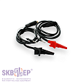
Test cable Set #2
039.27.00.000
Test cable Set #2
039.27.00.000
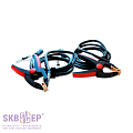
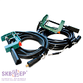
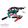
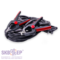
200 A Kelvin clamp test cable 2 x 2 m (1.12 kg) with jaw up to 50 mm. Include a current wire and a potential wire.
Ground cable
010.01.00.000
Ground cable
010.01.00.000
Ground cable 1 x 2 m (0.07 kg) for instrument grounding. The cable is equipped with a C-clamp and a screw end cap. Rated current is 50 А.
Mains battery charger
USB Type-A, USB Type-C Cables
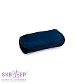
Tool bag
126.06.00.000
Tool bag
126.06.00.000
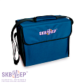
Convenient, robust, wear proof bag for transportation of cables, documentation and other accessories.
Test cables (on order):
Photo
Item, Index
Application
Set No. 1
039.19.00.000
Set No. 1
039.19.00.000
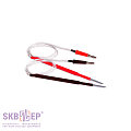
200 A Test cables 2 x 1.5 m (0.87 kg) with spring-loaded spike contacts. Include a current wire and a potential wire. Convenient for measurements in busbars and arc extinguish chambers.
Set No. 2
039.35.00.000
Set No. 2
039.35.00.000
200 A Kelvin clamp test cables 2 x 10 m (7.32 kg) with jaw up to 50 mm. Include a current wire and a potential wire.
Set No. 3
039.25.00.000
Set No. 3
039.25.00.000
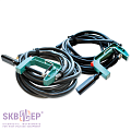
200 A Kelvin C-clamp test cables 2 x 4.5 m (3.79 kg) with jaw up to 80 mm. Include a current wire and a potential wire.
Set No. 4
039.26.00.000
Set No. 4
039.26.00.000
200 A Kelvin C-clamp test cables 2 x 6 m (5.12 kg) with jaw up to 80 mm. Include a current wire and a potential wire.
Test cable for sets No. 2, No. 3, No. 4
39.24.00.000 39.24.00.000-01 39.24.00.000-02
Test cable for sets No. 2, No. 3, No. 4
39.24.00.000 39.24.00.000-01 39.24.00.000-02
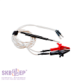
Test cables for precision measurements and measurements on circuit sections where a test current is applied to the end points. The set includes: A25C Kelvin clamp (2 pcs.) and test probes (2 pcs.).
For Set No. 2 – 2 m (039.24.00.000) (0.068 kg).
For Set No. 3 – 4.5 m (039.24.00.000-01) (0.151 kg).
For Set No. 4 – 6 m (039.24.00.000-02) (0.201 kg)
The cable can be used for specific resistance measurements of cables.
Set No. 5
Set No. 5
200 A Kelvin clamp test cable 1 m (0.5 kg) with jaw up to 50 mm. Includes a current wire and a potential wire.
Kelvin C-clamp test cable with jaw up to 80 mm. Includes a current wire and a potential wire. The following lengths are available:
3 m (039.21.00.000) (1.34 kg).
6 m (039.21.00.000-01) (2.0 kg).
9 m (039.21.00.000-02) (4.0 kg).
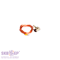
Potential spring-loaded contact
023.21.00.000/-01
Potential spring-loaded contact
023.21.00.000/-01
To be used together with test cables to eliminate high contact resistance between the input stud and the terminal. Applicable with Sets No. 2 - No. 5.
Potential pin contact
To be used together with test cables to eliminate high contact resistance between the input stud and the terminal. Applicable with Sets No. 2 - No. 5.
Test cable
039.37.00.000
Test cable
039.37.00.000
200 A Kelvin C-clamp test cables 2 x 15 m (6 kg) with jaw up to 80 mm. Include a current wire and a potential wire.
Test set
039.43.00.000
Test set
039.43.00.000
200 A Kelvin clamp test cables 2 x 10 m (7.9 kg) with jaw up to 70 mm.
Test cable
039.44.00.000
Test cable
039.44.00.000
200 A Kelvin clamp test cables 2 x 13 m (16.53 kg) with jaw up to 70 mm.
Additional complete set for DCRM mode (on order)
Photo
Item, Index
Application
Linear movement transducer DP12
012.00.00.000-02
Linear movement transducer DP12
012.00.00.000-02
For measuring the movement of moving parts in high-voltage circuit breakers. Range: 1 – 900 mm. Resolution: 0.5 mm. To be used together with a measuring stick.
Angular movement transducer DP21
009.00.00.000
Angular movement transducer DP21
009.00.00.000
For measuring the angle of shaft turn in high-voltage circuit breakers. Measuring range: 0.2 – 360°. Resolution: 0.09°.
Transducer cable
010.06.00.000-02
Transducer cable
010.06.00.000-02
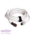
For connecting linear (DP12) or angular (DP21) movement transducer to the instrument.
Measuring stick
012.03.00.000/-01/-02
Measuring stick
012.03.00.000/-01/-02
Measuring stick in a case. To be used together with linear movement transducer DP12 (length on order – 550 mm, 700 mm and 1,000 mm).
Attachment devices set
Local triggering cable
026.16.00.000
Local triggering cable
026.16.00.000
For connecting to the high-voltage circuit breaker drive. Equipped with crocodile clamps. Nominal test current – 50 А. Cable insulation – silicone (length – 5 m).
Test cables for aviation diagnostics (on order):
Photo
Item, Index
Application
Test set
039.33.00.000/-01
Test set
039.33.00.000/-01
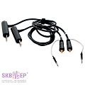
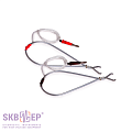
100 A Kelvin double hand spike test cable 2 x 1.5 m (0.471 kg) with spring-loaded contacts with jaw up to 20 mm. One probe is equipped with a control button for measurement start-up.
Recommended for contact resistance measurement in hard-to-reach places of objects with painted surfaces; in aviation: for contact resistance measurement of aircraft equipment and helicopter fuselage.
Test set
039.31.00.000/-01
Test set
039.31.00.000/-01
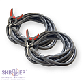
50 A Kelvin test cable with crocodile clips 2 x 1.5 m with jaw up to 20 mm. Recommended for resistance measurements in hard-to-reach places; in aviation: for resistance measurement of various elements of the aircraft.
Additional complete set (on order)
Photo
Item, Index
Application
BNC connection cable
Battery unit
055.04.00.000
Battery unit
055.04.00.000
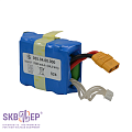
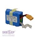
Battery unit for the device's autonomous operation. 7800 mAh. Set includes 1 pc.
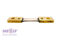
Shunt SV75-0075A-D-02
For checking the operability of the device. Value – 1 mΩ ± 0.5%. Manufactured by SKB EP.
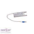
Adapter for a reference coil (2 pcs.)
023.12.00.000
Adapter for a reference coil (2 pcs.)
023.12.00.000
For testing laboratories: inspection / calibration of the instrument.
Adapter for a reference coil
For testing laboratories: inspection / calibration of the instrument, 2 x 0.025 m + 0.16 m (0.04 kg).
Official reviews from customers based on the results of operating SKB EP instruments are available upon request. Please, fill out the form on the website.